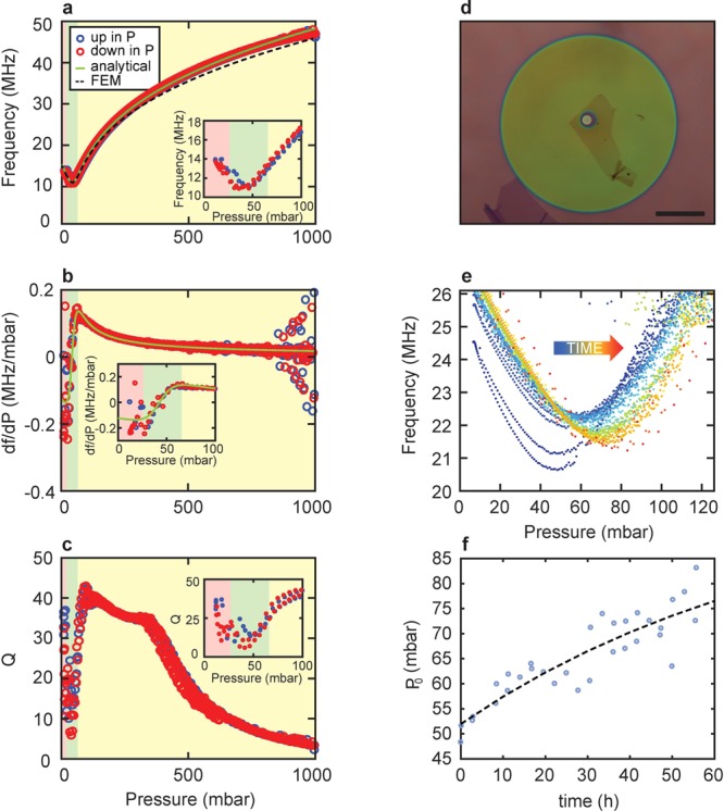
Figure 3.

(a) Pressure Pext dependence of the resonance frequency of device 1 shown in Figure 2. Plotted in red and blue circles are the pressure response of the resonance frequency while increasing and decreasing pressure, respectively. The analytical fit, based on the resonance frequency of a pressurized circular membrane is plotted in green. The fit parameters, E, n0, and P0 extracted from the analytical model are used in a FEM simulation (dashed black line). Inset: zoom-in near the minimum. (b) Differential responsivity (df/dP) plotted in red and blue circles and derivative of the analytical solution from (a) plotted in green. Inset: zoom-in near P0. (c) Q-factor as a function of pressure. Inset: zoom-in near the minimum. (d) Optical image of a sealed device (device 2) which consists of only 2 layers of graphene. Scalebar: 25 μm. (e) Plots similar to (a) are measured continuously over 55.7 h using triangular pressure sweeps with a period of 10000 s. (f) P0 is traced over 55.7 h and fitted to an exponential resulting in a time constant of τsealed = 2.88 × 10⁵ seconds.
