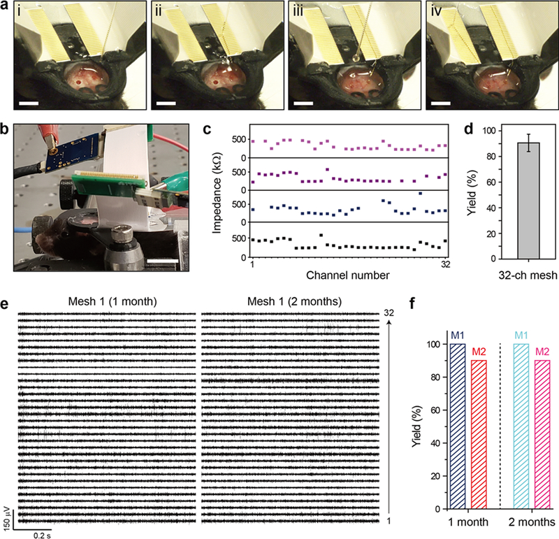
Figure 4. In-vivo demonstration of direct contact I/O interface.
(a) Images showing the alignment and direct contact connection of I/O pads to the two FFCs fixed on the mouse head-stage. The mesh electronics probes were injected into the hippocampus of both cerebral hemispheres. (b) Image of a head-fixed mouse while recording from both implanted mesh probes, which were connected to the FFCs by the direct contact method. Instrument amplifiers are attached to each of the FFC interfaces for the recording session and are visible in the upper portion of the image. Scale bar, 4 mm. (c) Measured in-vivo impedance values at 1 kHz for four 32-channel implanted mesh probes. Channels for which no impedance value is shown were disconnected, with impedance values above 2 MΩ. (d) Yield of the electrical connection of the 32-channel meshes (N = 4). Error bar denotes ±1 SD. (e) 32-channel neural recordings from Mesh 1 at 1 month (left) and 2 months (right) post-injection. (f) Yields for electrical connection of the two 32-channel mesh probes (Mesh 1 in Figure 4e and Mesh 2 in Figure S6) at 1 month and 2 months post-injection.

