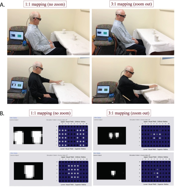
Figure 3.
(A) Demonstration of the two tasks. Top, localization task: a subject was detecting two cups of hot water using no zoom (left) versus zoom out (right). The cups could be presented either separately or together at one or two of the three locations: right, center, or left, respectively. Bottom, reaching task: the subject was reaching to a cup of hot water using no zoom (left) versus zoom out (right). The location of the cup could be right, left, or center relative to the subject. (B) Thermal camera video output and prosthesis stimulation patterns (screenshots from the laptop). Top, two cups of hot water together. Bottom, one cup of hot water. Left, no zoom. Right, zoom out. Within each panel, the grayscale image on the left shows the video input from the thermal processor, where brighter pixels correspond to a higher temperature. The image with individual dots on the right side of each panel represents the electrical stimulation patterns delivered by the implant, where each dot corresponds to one electrode and brighter color means stronger stimulation with respect to that electrode's threshold.

