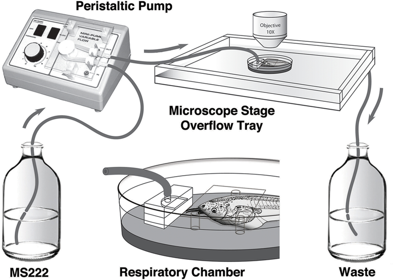
Fig. 2.

Schematic drawing of the respiratory chamber and pump system. An anesthetic solution of MS-222 is pumped to the respiratory chamber via a peristaltic pump. The respiratory chamber contains a manifold that provides continuous flow of anesthetic solution over the tadpole, which is held in place with clay. Three fixed pedestals hold a coverslip to provide a transparent and flat surface for imaging. The respiratory chamber is placed into a shallow plexiglass overflow tray to catch the anesthetic solution. The overflow tray collects anesthetic runoff to a waste container that can be discarded or recirculated, as needed by the experiment.
