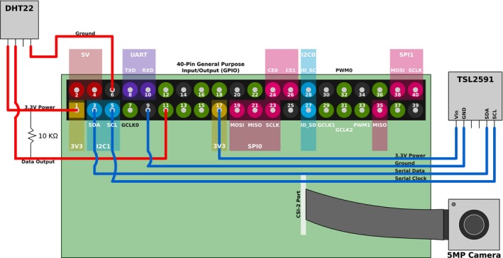
Figure 2.

A diagram showing the connections between the Raspberry Pi and the attached peripheries and the Raspberry Pi GPIO pinout. Illustrated are the connections for the light intensity sensor (TSL2591) to the GPIO pins: pin 3 for SDA (serial data), pin 5 for SCL (serial clock), pin 9 for ground, and pin 17 for 3.3‐V power. The diagram also illustrates the connection of the temperature and humidity sensor (DHT22) to the GPIO pins: pin 1 supplying 3.3‐V power, pin 6 for ground, and pin 11 for data. In addition, the figure shows where the resistor should be soldered between the power and data wire for the temperature and humidity sensor (DHT22). Finally, it shows where the ribbon cable from the camera board is connected to the Raspberry Pi.
