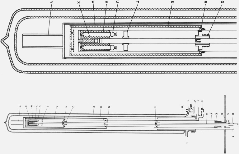
Figure 2. Cryostat for the intercomparison of capsule type SPRT’s.
A. Guide for directing transfer tube into liquid helium Dewar.
B. Metal bellows to permit differential expansion between the central tube and the supporting thermometer block well.
C. Exit for the vacuum line and electrical leads to the thermometers, the thermocouples, and the heater on the copper thermometer block.
D. Supporting shelf.
E. Demountable “O” ring seal to the well around the thermometer block.
F. Well around the thermometer block.
G. Central tube for supporting the thermometer block.
H. Seal for the electrical leads from the vacuum can that surrounds the shield and lower portion of the thermometer block well.
I. Line from vacuum can “O”.
J. Demountable “O” ring seal to the liquid helium Dewar.
K. Glass stopcock to permit reevacuation of liquid helium Dewar.
L. Line for pumping the space within the liquid helium Dewar.
M. Liquid helium Dewar.
N. Thermal tie-down for lead wires.
O. Vacuum can that surrounds the lower portion of the thermometer block well and the thermal shield.
P. Copper sleeve on vacuum can to maintain uniform temperature when liquid helium level is low.
Q. Thermal tie-down for leads similar to N with a heater and five-junction Chromel-P/constantan thermocouple for temperature control.
R. Copper ring on the thermometer block well with temperature control components similar to Q.
S. Heavy copper shield with temperature control components similar to Q.
T. Thermometer lead terminal block of anodized aluminum.
U. Capsule type platinum resistance thermometers thermally attached to copper block with vacuum grease.
V. Copper thermometer block with holes for six thermometers.
W. Location of thermocouple junctions placed on shield.
X. Reentrant “thumb” in the bottom of well. “Thumb” contains reference junctions for thermocouples on R and S.
Y. Heavy copper tail on vacuum can to reach liquid helium at a low level.

