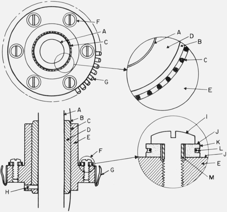
Figure 5. Thermal tie-downs.
A. Central support tube (stainless steel) for thermometer block.
B. Rounded corner, tangent to the bottom of the grooves for wire.
C. Round bottom grooves in cylinder “D” with wire cemented in place.
D. Copper cylinder soldered (tin-lead eutectic) to the central support tube.
E. Copper cylinder fitted to “D” and held in place by pin “H”.
F. Thermocouple tie-down.
G. Spring fingers of beryllium copper heavily silver plated and gold “flashed”.
H. 1.5 mm steel pin to hold cylinder “E” in position.
I. Pan head 2–56 brass screw to clamp thermocouple tie-down assembly to “E”.
J. Insulating washer of 0.005 mm Mylar coated with vacuum grease.
K. Copper washer with pretinned groove for thermocouple wire.
L. Polyimide insulated thermocouple wire, placed at the bottom of the pretinned groove and “potted” in eutectic tin-lead solder.
M. Epoxy insulation on screw.

