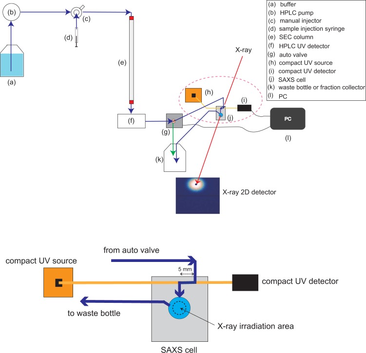
Figure 1.
Schematic overview of La-SSS, which consists of (a) buffer bottle, (b) HPLC pump, (c) manual injector, (d) sample injection syringe, (e) SEC column, (f) HPLC UV detector (g) auto valve, (h) compact UV source, (i) compact UV detector, (j) SAXS cell, (k) waste bottle or fraction collector, and (l) PC that is used for monitoring UV intensity at SAXS cell position and for switching the flow path between a waste bottle and a SAXS cell. The down figure corresponds to the magnified pictures of SAXS cell, compact UV source, and compact UV detector, which are highlighted by pink dotted circle in upper figure. Dark blue and yellow lines correspond to a flow path and an optical fiber, respectively, and the sample flow path was set to 5 mm. Black dotted circle indicates X-ray irradiation zone. The system has another function “stopping mode”. When the OD280 value exceeds the set value, the auto valve automatically switches the path from a SAXS cell to a waste bottle, as shown by green arrow. As a result, the solution exceeding the set OD280 value, target protein solution, remains in the SAXS cell.

