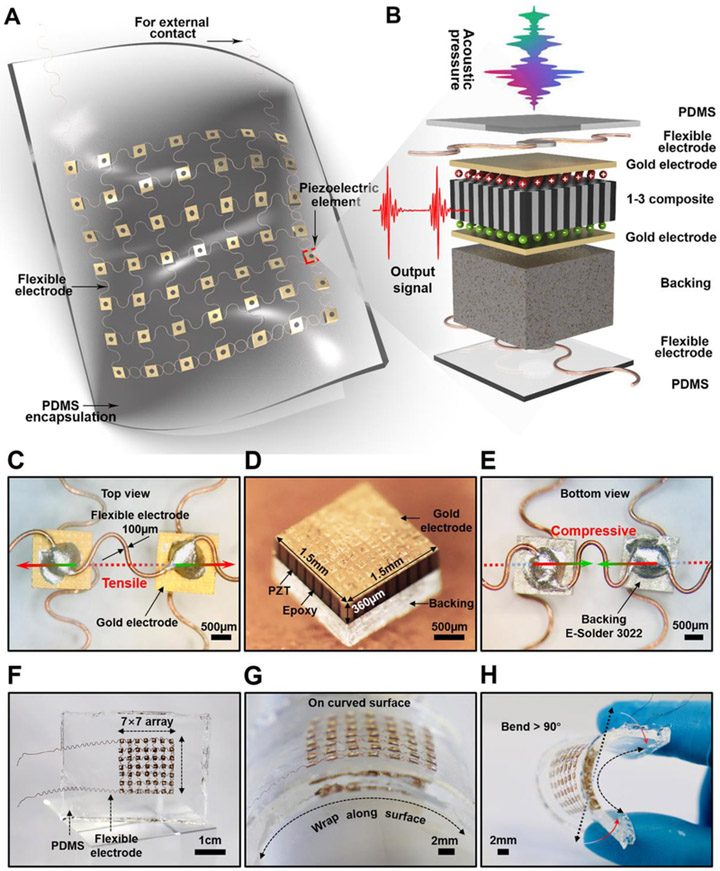
Fig. 1. Schematic and design of the flexible PUEH device.
(A) A Schematic to show the device structure. (B) Exploded view to illustrate each component in a piezoelectric element. (C) The optical image (top view) of two piezoelectric elements. (D) The optical image of a 1-3 piezoelectric composite. (E) The optical image (bottom view) of two piezoelectric elements. (F to H) Optical images of the flexible device when it stands freely, wraps over a curved surface, and bends.

