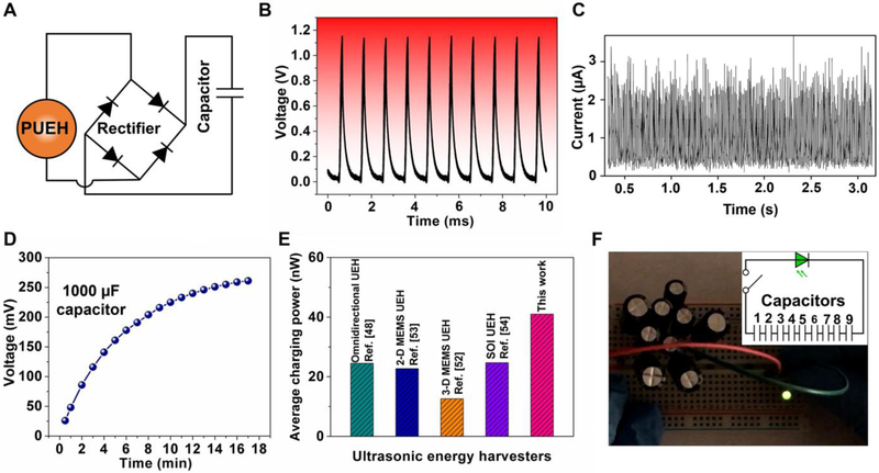
Fig. 4. Applications of the flexible PUEH device.
(A) Schematic design diagram of the energy rectifier and storage circuit comprising four diodes and one capacitor. (B and C) Output voltage and current signals after rectification, respectively. (D) The charging time dependence of voltage in the storage capacitor. (E) Comparison of the average charging power of ultrasonic energy harvesters. (F) Optical image showing a commercial green LED lit up by the energy stored in capacitors; the inset shows the schematic circuit diagram of nine capacitors in serial.

