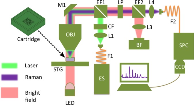
Figure 5.
The experimental setup of HCA-RS system has many components. They are ES – excitation source, F – fiber, L – lens, CF – clean-up filter, EF – edge filter, M – mirror, OBJ – objective, STG – xyz stages, LP – long pass filter, BF – bright field camera, LED – light emitting diode, SPC – spectrograph and CCD – Raman spectral detector. The cartridge is placed on the STG and can accommodate six CaF2 coverslips for six different measurements in one run. The light green, the purple and the pink lines indicate the excitation, the Stokes Raman signal and the bright field illumination path, respectively. In this work we referred Stokes Raman as Raman signal which is generated in the sample plane and travels back with the excitation path up to EF1 and is then separated (along the light green line from the sample plane up to the EF1).

