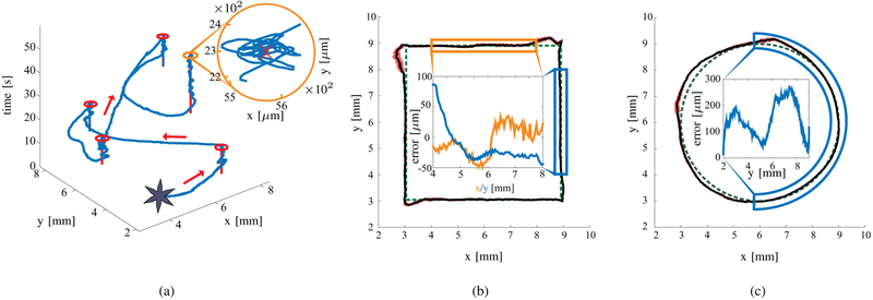
Fig. 6.
Representative closed-loop motion control experimental results of a gripper. (a) An example of point-to-point motion control experiments. The red lines represents the setpoint, the blue line the trajectory of the gripper, and the red circles the Region of Convergence (ROC). (b) and (c) depict the trajectory following experiments. The green dashed path represents the reference trajectory, the black line shows the path of the gripper, and the red area represents the standard deviation for the corresponding point among all the experiments. The insets show the positioning error in the highlighted parts of the trajectories. Please refer to the accompanying video for the experiments.

