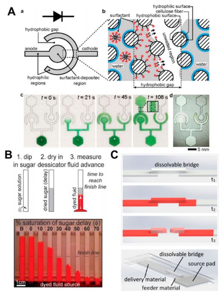
Figure 5.
Flow control using chemical-based methods. (A) Schematic of a one-directional fluidic diode and illustration of the working mechanism of the fluidic diode. Fluid flows through the hydrophobic gap from the surfactant side. The images show that the green-dyed fluid flows through the diodes (reproduced from ref [121] with permission from the Royal Society of Chemistry, 2012). (B) Preparation steps of delayed strip using sugar solution. Experimental images show the flow test with varying concentrations of sugar solution, and the dashed line and strip “B” indicate the finish line and an untreated strip, respectively (reproduced from ref [122] with permission from the Royal Society of Chemistry, 2013). (C) Schematic of operation mechanism and set-up of a dissolvable bridge. The bridge dissolves at a certain time to shut-off the fluid flow (reprinted with permission form ref [124]. Copyright 2013 American Chemical Society).

