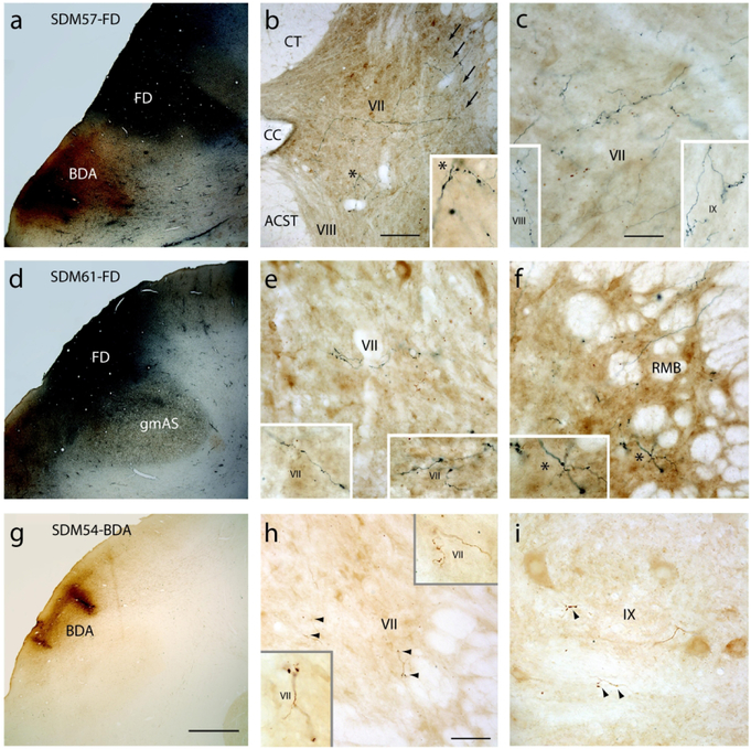
Figure 2.
Plate of photomicrographs showing the major LPMCd injection site cases and representative terminal labeling at C5 to T1 in the spinal cord. A) Coronal section in case SDM57 showing the FD (blue reaction product) and BDA (brown reaction product) injection sites in LPMCd and LPMCv respectively. B) Transverse section in case SDM57-FD showing contralateral FD labeled fibers and terminals in C6. The asterisk in the main panel denotes the location of the higher power image shown in the inset on the bottom right. The arrows (top right) show the main route and trajectory taken by labeled axons from the lateral corticospinal tract to the contralateral spinal gray matter. Note the heavy presence of both axons in passage and labeled bouton terminals in the dorsolateral gray matter region (of lamina VII) that precluded the positive assessment of terminal labeling by Kuypers with his use of the axon degeneration technique that was available at the time he conducted his classical studies. C) Transverse section in case SDM57-FD showing contralateral FD labeled fibers and terminals in the ventromedial sector of lamina VII at C6. The inset on the bottom left shows contralateral terminal labeling in lamina VIII at C5. The inset on the bottom right shows contralateral terminal labeling in lamina IX at C7. D) Low power image showing the FD injection site in case SDM61 just superior to the gray matter capping the posterior tip of the spur of the arcuate sulcus (gmAS). E) Transverse spinal cord section in case SDM61-FD showing terminal labeling in the contralateral ventromedial sector of lamina VII at C5. The inset on the bottom left and bottom right show higher power images of terminal labeling in the ventromedial region of lamina VII at C6 and C7 respectively. F) Transverse section in case SDM61-FD showing contralateral FD labeled fibers and terminals in the reticulated marginal border (RMB) at C7. The asterisk in the main panel denotes the location of the higher power image shown in the inset on the bottom left. G) Coronal section in case SDM54 showing a portion of the BDA injection site in LPMCd. H) Transverse section through spinal level C6 in case SDM54-BDA showing contralateral terminal labeling in the ventrolateral sector of lamina VII at C6. The arrowheads denote the locations of labeled boutons. The insets are higher power images of BDA lamina VII labeling at C6 (bottom left) and C7 (top right). I) Contralateral terminal labeling in lamina IX in case SDM54-BDA at C5. The arrowheads show locations of terminal bouton profiles. Micron bar in: B = 200μm; C = 50μm and applies to panels E, F and I; G = 2mm and applies to panels A and D; H = 100μm. Abbreviations: ACST, anterior corticospinal tract; CC, central canal; CT, cuneate tract; RMB, reticulated marginal border.

