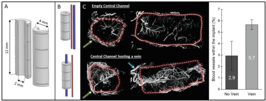
Figure 1.

A) CAD design of cylindrical implant, B) schematic of the control placement next to femoral arteriovenous bundle and the experimental group with a single femoral vein placed axially within implant. C) Micro‐CT cross‐sections of decalcified implants perfused with MicroFil showing the blood vessels inside and outside the implant (green arrow: fibrous capsule; blue arrow: feeding vein) and quantification of the relative volume of blood vessels inside the implant.
