Figure 2.
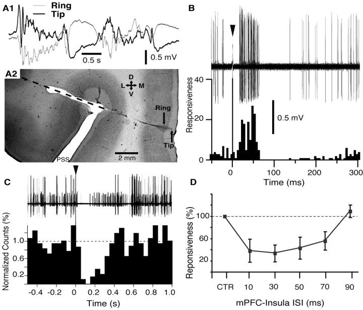
Effect of electrical mPFC stimulation on neuronal activity in the BL nucleus. A1, A2, Electrophysiological criteria used to adjust the position of a concentric stimulating electrode in superficial mPFC layers. A1, Electrode position was adjusted such that the EEG activity recorded by the tip (thick line) and ring (thin line) of the electrode (0.7 mm spacing) was of opposite polarity. In this position, the tip of the electrode was usually located in layer I. A2, Coronal section of the mPFC stained with neutral red showing trajectory of the electrode aimed to the mPFC. Orientation of the section is indicated by the cross where D, V, L, and M stand for dorsal, ventral, lateral, and medial, respectively. B, Example of BL neuron orthodromically activated by mPFC stimulation (arrowhead indicates mPFC stimulation artifact). Forty superimposed sweeps are shown on top; a poststimulus histogram (5 ms bins) based on 100 such sweeps is shown below using the same time base. Responsiveness was defined as the number of spikes divided by the number of stimuli. C, mPFC stimulation (arrowhead) evokes suppression of spontaneous firing in a group of BL neurons recorded simultaneously by the same electrode. Forty superimposed sweeps are shown at the top; a poststimulus histogram (50 ms bins) based on 54 such sweeps is shown below using the same time base. The dashed line indicates average bin value in the prestimulus period (normalized to 1). D, mPFC stimulation inhibits the orthodromic responsiveness of BL neurons to insular inputs. Graph plots average orthodromic responsiveness (y-axis) of seven neurons to insula stimuli applied alone (CTR, control) or preceded by mPFC stimuli with various ISIs (x-axis). Data were obtained in four different animals. PSS, Presylvian sulcus. Error bars indicate SE.

