
Figure 1.
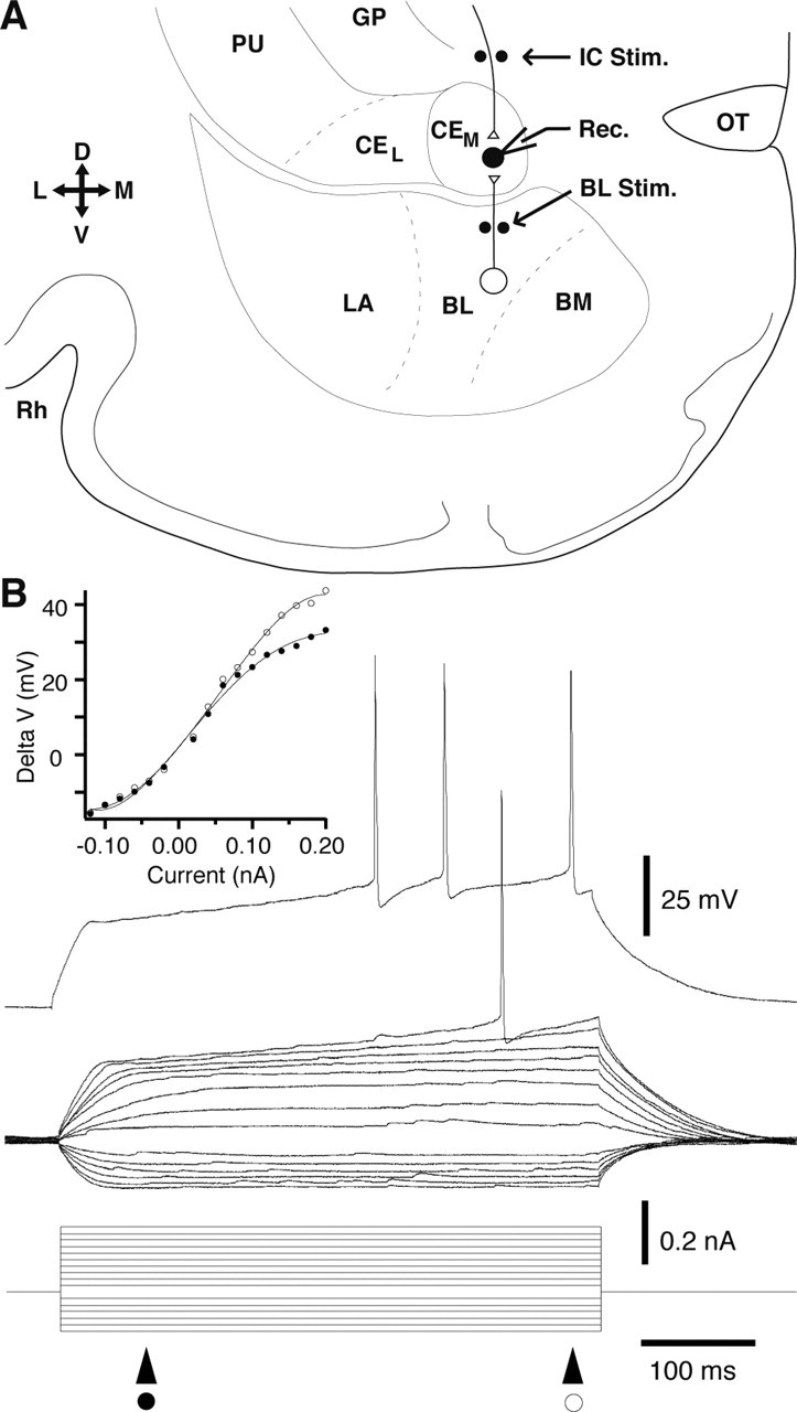
Experimental setup (A) and physiological properties of late-firing CEm neurons (B). A, Scheme showing a coronal slice of the guinea pig amygdala. Black dots indicate position of stimulating electrodes (Stim.) in the internal capsule (IC) and BL nucleus. Pipette shows recording site (Rec.) in CEm. Slice orientation is indicated by the cross on the left where D, V, L, and M indicate dorsal, ventral, lateral, and medial. B, Voltage responses of a representative late-firing cell to a series of current pulses applied from rest (-81 mV). Note delayed firing onset and ramp-like voltage response to depolarizing current pulses that brought the membrane potential positive to -65 mV. The inset on top left shows a plot of voltage response (y-axis) as a function of injected current (x-axis). Voltage measurements were performed at two different times, as indicated by the symbols below the current monitor. BM, Basomedial nucleus; CEL and CEM, lateral and medial sectors of the central nucleus; GP, globus pallidus; PU, putamen; OT, optic tract; Rh, rhinal sulcus.