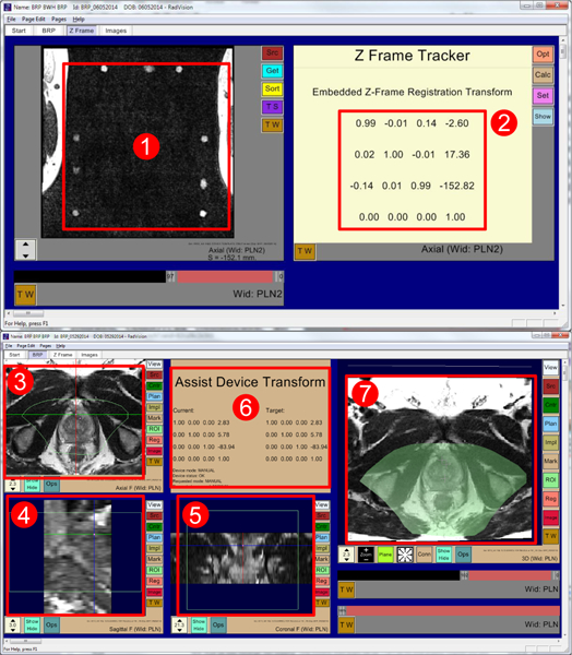
Fig. 6.

RadVision user interface showing (1) acquired MR images of fiducial frame, (2) calculated robot registration transform, (3) axial view, (4) sagittal view, (5) coronal view, (6) robot status, current robot pose, and desired target pose, and (7) 3D view with overlaid reachable robot workspace shown in light green. Also in all image views (3, 4, 5) light green boundary indicates reachable robot workspace.
