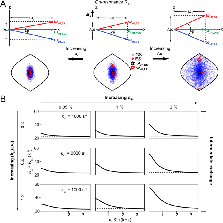
Figure 14.
Dependence of on-resonance R1ρ on exchange and spin-lock parameters.A) Δω and ω1 modulate Rex via changes in φ, the angle between ωeff,GS and ωeff,ES. Also shown are positions of the magnetization vectors corresponding to GS (blue circles) and ES (red circles) obtained using vector model simulations in the form of Sanson-Flamsteed projections[192]. ωeff,GS and ωeff,ES are indicated by black and red stars respectively. Simulations were performed with the following parameters - pES = 0.01, kex = 20,000 s−1, , γ(1H)B0/2π = 700 MHz, ω1/2π = 1000 Hz when on-resonance with the AVG state. Positions of the spins for a larger (right) and ω1/2π = 3000 Hz (left) are also shown. Simulations employed 10,000 spins with a relaxation delay of 0.012s.B) Variation of R2 + Rex with ω1 under on-resonance conditions as a function of exchange parameters, as obtained using B-M simulations. Rows and columns correspond to the indicated values of kex and pES, respectively. Dashed line denotes the value of R2. The other exchange parameters used were , γ(1H)B0/2π = 700 MHz, R1,GS= R1,ES = 2.5 s−1 and R2,GS = R2,ES = 22.5 s−1. The initial alignment of the magnetization during the B-M simulations was performed as described in Section 6.1.

