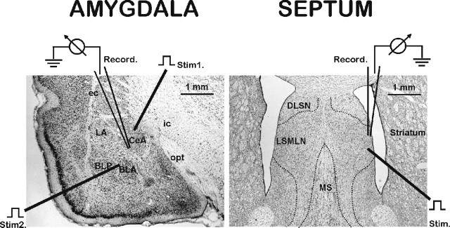
Figure 1.
Illustration of brain slices containing the amygdala (left) and septum (right) showing recording and stimulationsites. Slices (30 μm) were stained with cresyl violet and with drawing applied to denote positioning of stimulating and recording electrodes. Single recording electrode is shown within the CeA, with stimulating electrode 1 positioned to activate the VAP-CeA pathway and electrode 2 positioned to activate the BLA-CeA pathway. CeA, Central amygdala nucleus; LA, lateral amygdala nucleus; BLA, basolateral anterior amygdala nucleus; VAP, ventral amygdala pathway; BLP, basolateral posterior amygdala nucleus; ec, external capsule; ic, internal capsule; opt, optic tract. Single stimulating electrode is shown within the ventral LSMLN with the recording electrode positioned in the LSMLN. LSMLN, Lateral septum mediolateral nucleus; MS, medial septum; DLSN, dorsolateral septal nucleus.

