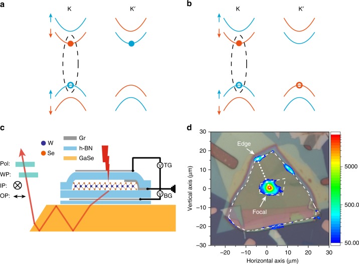
Fig. 1.
Dark excitons in WSe2 and experimental geometry. a, b Electronic configuration of a dark electron trion (a) and dark hole trion (b) in single-layer WSe2. Blue and orange curves represent electronic bands with electron spin up and spin down, respectively. The hole spin is opposite to what’s shown for the electron spin. Dashed ellipses indicate the electron-hole pairs involved in the recombination. c Schematic side view of a dual-gated WSe2 device on a GaSe waveguide. WSe2 is excited by a focused light beam (red lightning symbol) and the resultant PL guided by the waveguide (red arrowed line) is detected. The IP and OP emission dipoles are selected by a half-wave plate (WP) and a polarizer (pol). WSe2 is grounded. TG and BG are the top and bottom gate voltages, respectively. d Optical reflection and PL images (overlaid) of a typical device. Inner and outer white dashed lines show the boundary of WSe2 and GaSe, respectively. The dotted white line, which is perpendicular to the edge, is referred to as the focal-edge line. The color bar represents the PL intensity.

