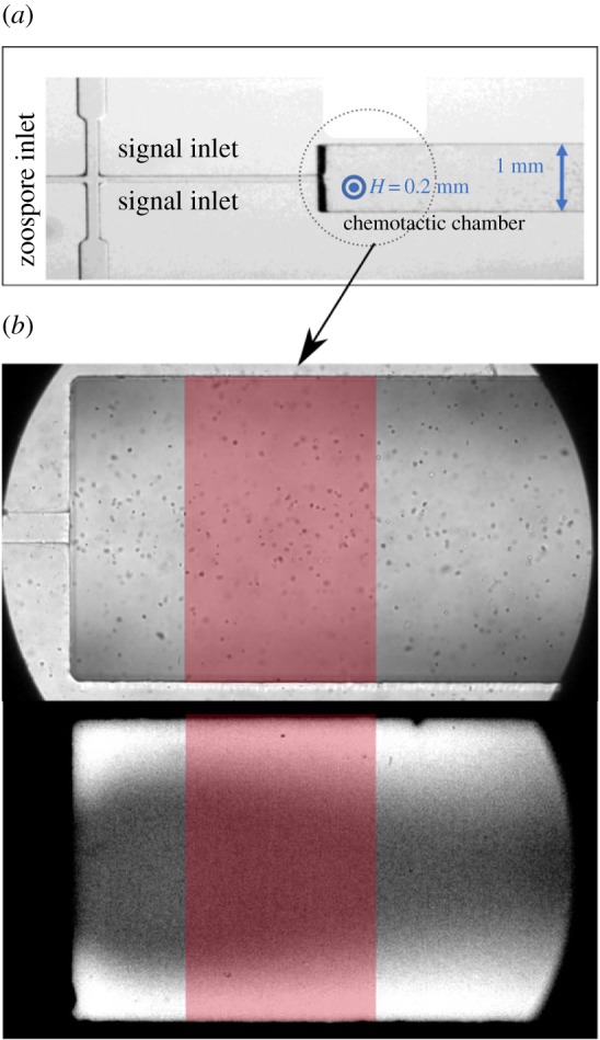
Figure 5.

Microfluidic device. (a) Image of the device, showing the three inlets and the chemotactic chamber (H × W = 0.2 mm × 1 mm). Zoospores were injected into the central inlet and 100 mM KCl was injected into the side inlets (signal inlets). (b) Images of the observation chamber (or chemotactic chamber) in bright-field conditions (upper image), showing zoospores, and in fluorescence conditions (lower picture), for the mapping of potassium concentration in the chamber based on the fluorescence of the APG-2 probe. The red window indicates the area of the chamber taken into account in the analysis of zoospore tracking and measurement of the spatio-temporal concentration of potassium. In the lower image, the white areas in the uppermost and lowermost regions of the image indicate the areas in which the concentration of potassium is high. (Online version in colour.)
