Summary
Identifying the localization, distribution and polarity of waveforms are the prime goals of clinical scalp EEG analysis. Appropriate choices of bipolar and referential montages are key to emphasizing the diagnostic features of interest, and demand some understanding of the spatiotemporal physical behavior of the underlying neuronal generators. Several examples drawn from canonical epilepsy syndromes are used to illustrate this general message.
Keywords: Epilepsy, bipolar, referential, scalp recording
Introduction
Derived from the French monter (to ‘mount’ or ‘put up’) the word ‘montage’ refers to the arrangement of segments of information to form a whole. The term accurately describes the process of display of scalp EEG, where potentials from multiple head locations are arranged into a standard format to allow an integrated representation. An intuitive feature of all EEG montages is the grouping of channels by spatial proximity, i.e., in groups of ‘left-over-right’ (or the opposite) and by paracentral or frontotemporal location. Thus, any feature of the EEG that appears more prominent in one electrode set than the others may be interpreted reasonably as arising approximately in the brain location underneath those electrodes. However, a more detailed appreciation of commonly used montages demands basic understanding of the properties of electric fields in the brain, and the behavior of neurophysiological potential generators.
This article outlines some considerations in adopting the different montages standard in clinical scalp EEG practice. All illustrations are drawn from epileptiform disturbances rather than normal waveforms or other classes of EEG abnormality.
General principles
The newcomer to scalp EEG immediately notices that montages are always set up to record signal (potential) differences, for instance Fp1-F3 in a ‘bipolar’ arrangement and Fp1-REF in a ‘referential’ montage. Doing so may seem unnecessarily elaborate and wasteful due to data ‘subtraction’, given that the desired information is how regional potentials change over time in some absolute sense. That is, in this example, one may be interested in how the brain region under the Fp1 electrode behaves over time, not necessarily how it compares to the neighboring brain area underlying F3, or with respect to the reference electrode REF. Yet the term ‘absolute potential’ has no meaning in itself, and even when used implies the potential with reference to some distant location attributed to have ‘zero’ potential. Thus, what is measurable is the potential difference between the brain region of interest and a neutral (‘quiet’) reference. An attempt to find a quiet reference outside the body (say, by grounding the reference electrode) is however impractical – the head as a whole experiences potentials far in excess of cerebral potentials from both physiological (e.g. the EKG, whose potentials are a hundred-fold larger) and environmental (e.g. static electric charge from clothing) sources, which would swamp the EEG. This leads to the necessity of finding a reference on the head, so that large common mode potentials are naturally subtracted. Yet, due to the nature of volume conduction, no location on the head can realistically be considered ‘quiet’ with respect to another. The concept of a genuinely quiet reference is therefore a myth 1, and all EEG derivations whether ‘bipolar’ or ‘referential’ are in fact bipolar. Nevertheless, it is still true that for brain activity that is localized (say, a spike over the left temporal lobe), the choice of a ‘reference’ electrode chosen over the right occipital area or right paracentral area may make no noticeable difference to the morphology and size of the spike waveform. Being independent of the choice of reference, the spike can therefore be attributed to the left temporal lobe; in this sense, the reference chosen can be considered indifferent or ‘quiet’. If the reference indifference 2 is true for a group of spatially adjacent electrodes, then a referential ‘montage’ has been achieved, where simple inspection identifies the electrode of maximum activity and its polarity. In contrast, bipolar derivation involves deliberate differencing of potentials between spatially adjacent locations. This leads to the construction of a bipolar ‘montage’ as a sequence of adjacent spatial differences, with the maxima and polarity of the waveform of interest subject to the rules of phase reversal detailed elsewhere in this special issue of the Journal.
A second general point concerns the spatiotemporal distribution of cerebral potentials on the scalp. The scalp EEG is considered to be the surface representation of averaged electronic potentials from dipole layers of pyramidal cells in the cortical grey matter ribbon 3. Specifically, the EEG is largely due to activity within the gyral crowns; potentials from the depths of the sulci can be obscured by sources closer to the recording electrodes, and potentials summed from opposing cortical sheets along sulcal walls may cancel. The poor conductive properties of tissue interposed between the brain surface and the scalp lead to significant spatial low-pass filtering of transmitted brain surface potentials; this is the physical reason for the widely-quoted figure of the necessity of 6–10 cm2 of cortex to be synchronously active for detection on the scalp 4,5. Portions of cortex this size or larger when simultaneously active can be considered macroscopic dipoles, and are commonly referred to as the neuronal ‘generators’ of specific potentials. For instance, the left temporal lobe spike of the paragraph above would be considered as arising from a unitary generating dipole within the temporal lobe. The orientation and physical extent of the dipole then determines the pattern of activity on the recording electrodes, which will be seen differently in different montages. For instance, due to placement of recording electrodes along the contour of the head, scalp EEG is naturally more sensitive to radially, rather than tangentially, oriented dipoles. Potentials recorded at a distance from ‘generators’ are said to fall off exponentially, but the precise nature of potential fall-off depends on the size of the dipole and its orientation with respect to the recoding electrode. Whatever the precise functional form of fall-off, the decrease of potentials is nonlinear with physical distance, and yields the typical appearances of large deflections in bipolar derivations being interpreted as proximity to the generator 6. In referential recordings, the electrode closest to the generator is merely the one exhibiting the largest deflection.
Several of these introductory principles are illustrated in the examples below. Portions of the monograph of Nunez and Srinivasan (2006) in addition to the classic review by Gloor (1985) are highly recommended sources for further details.
Bipolar, referential and Laplacian montages
The era of digital EEG with ready reformatting and remontaging of display has largely supplanted the previous generation of analog (paper) recordings 7,8. Localizing the specific EEG abnormality of interest is one of clinical neurophysiologist’s main goals, and the essential maneuver to do so is the judicious choice of bipolar and referential montages. It should be borne in mind that neither bipolar setting nor referential settings are superior to the other, but function in a complementary fashion. Certain situations may make choosing one over the other more advantageous. Due to their differencing action, bipolar montages produce spatial filtering and accentuate small amplitude, focal discharges better 9,10. Such discharges may be buried in higher amplitude potentials when referential montages are used with large inter-electrode distances 11. On the other hand, large potentials that are widely distributed are subject to cancellation with the use of bipolar montages. In these cases, referential montages using, say, the average reference, would show the higher amplitude widely distributed discharge. However, discharges with very wide fields can cause ‘reference contamination’ with the use of the average reference and might interfere with interpretation. In these instances, the choice of a common reference such as the ear or Cz would be more appropriate 10. As a general rule a non-contaminated, quiet reference is a key for clean and accurate display, notwithstanding the impossibility outlined above of obtaining a truly ‘quiet’ reference. Another montage is the Laplacian, which is somewhere between bipolar and referential. The Laplacian represents the second spatial derivative (or second difference, as opposed to the bipolar which is the first spatial difference) and involves the weighted average of voltages from surrounding electrodes of a particular electrode as a ‘local’ reference. In practice, computation of the Laplacian is relatively complicated and depends on the particular electrode involved in the montage. The Laplacian is best suited to display relatively focal discharges with minimal field 12.
Bipolar and referential montages are used most effectively with a certain foreknowledge of the types of activity that characterize particular epilepsy syndromes. In other words, the identifying features of different epilepsy syndromes help in choosing appropriate montages or their combinations. These features include spatial extent of the discharges (a focal versus a generalized epilepsy), localization of the discharges (frontal, temporal, central or posterior?), amplitude of the discharges (spatial extent of the generator), depth of the discharge source (will the discharge be sufficiently visible?), and the existence of other abnormal or physiological rhythms in relation to the discharges.
Illustrations
Temporal lobe epilepsy
The temporal lobe is the most common site of focal epilepsy in adults, and exhibits two distinct electro-clinical syndromes, medial (or mesial) temporal lobe epilepsy (MTLE) and neocortical temporal lobe epilepsy (NTLE). In MTLE the spike generators are the hippocampus, amygdala and adjacent entorhinal cortex. The reason that the spikes of MTLE are detected on scalp EEG despite their deep generation is because of amplification by recruitment of basal and lateral temporal areas. Spikes restricted to the medial temporal structures would be swamped by the background activity of intervening cortex closer to the recording electrode and be invisible to scalp EEG. Indeed, because of the ‘closed’ geometry of the hippocampus, purely hippocampal spikes are not detected even with intracerebral electrodes in the temporal lobe unless the recording contacts are physically within the hippocampus. With the incorporation of the inferolateral temporal cortex, the dipole of the MTLE generator has a naturally vertical orientation. This is the Ebersole ‘Type I’ spike 13, that displays an inferolateral negatively and a widespread ipsilateral fronto-central positivity (Figure 1a-b). In contrast, the NTLE spike generator is superficial and laterally displaced; this Ebersole ‘Type II’ spike 13 is negative everywhere over the ipsilateral hemisphere (Figure 1c-d). These Type I and II dipolar characteristics are most readily appreciated in referential derivations and can also be observed in the seizure rhythms of MTLE and NTLE.
Figure 1.
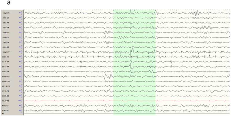
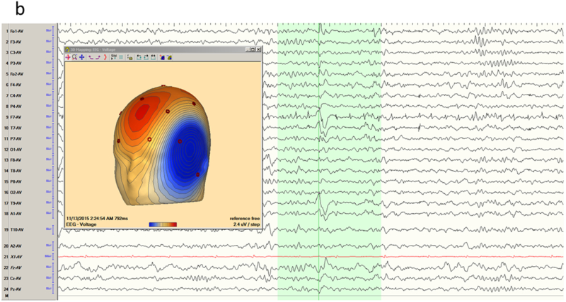
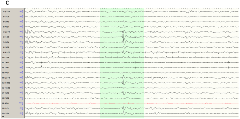
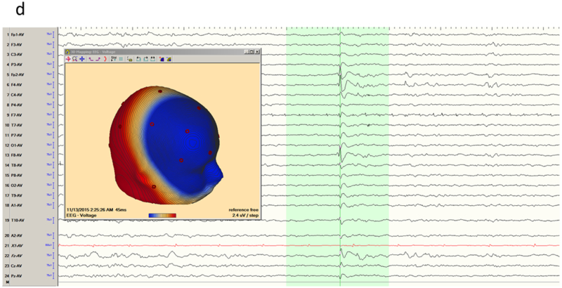
Temporal lobe epilepsy. a) Left temporal lobe spike in bipolar montage including anterior temporal electrodes (T9/T10). The phase reversal reveals broad maximal negativity at F7, T7 and T9. b) Average reference montage confirms the locations of maximal activity and also positivity over the fronto-central contacts, suggesting a mesial source of the spikes (Ebersole Type I). The color voltage map confirms the polarity of the spike, with the current sink (negativity; blue) over the temporal lobe and current source (positivity; red) over the frontocentral area. c) Right temporal spike seen in a bipolar montage in the same patient, who had bitemporal epilepsy. Phase reversals suggest maxima at F8 and F4. d) Average reference montage confirms the location of the maxima, and also a negative deflection over the frontal contacts, confirming an Ebersole Type II spike of a neocortical source. The voltage color map shows a broad current sink (negativity; blue) over the whole right frontocentral area.
The remoteness of the mesial temporal lobe from the lateral skull have led to a number of special EEG recording techniques for suspected temporal lobe epilepsy. Foramen ovale (FO) electrodes are a semi-invasive technique for recording from the epidural space medial to the hippocampus. FO electrodes are not widely used; their rate of complications is said to compare with true intracerebral electrodes which offer more direct and targeted sampling 14. Nasopharyngeal (NP) electrodes are introduced through the nasal passage to rest in the roof of the nasopharynx and positioned to record from the mesial basal frontal and temporal regions. Though safe, NP electrodes can cause discomfort and have not been widely adopted 14. Usage of sphenoidal (SP) electrodes is more common but has been controversial 15,16. SP electrodes are introduced through the mandibular notch inferior to the zygoma to rest under the base of the skull lateral to the foramen ovale. When optimally positioned, SP electrodes provide high amplitude recordings of the mesial structures with narrower voltage fields, serving to distinguish truly mesial discharges from neocortical ones, and also providing a more accurate right-to-left comparison in bitemporal syndromes 14. However, arguments have been made that anterior temporal surface electrodes (T9 and T10) provide equivalent information without the invasiveness of SP recordings 15. Regardless, it is probably the case that versatility of digital EEG with its remontaging, filtering and field mapping capabilities, together with advanced imaging of the temporal lobe is reducing the requirement for these special techniques.
Frontal lobe epilepsy
The frontal lobe is the largest lobe in the brain, constituting about a third of its total volume. Frontal lobe epilepsy (FLE) is also second most common epilepsy in adults. Due to the size and functional anatomy of the frontal lobe, FLE can produce widely different features depending on the location of the epileptic focus. For the purposes of classification of interictal EEG activity, we suggest the division of the frontal lobe (and FLE) into i) the frontal pole, including the orbitofrontal area, (ii) the lateral frontal lobe, and (iii) the medial frontal lobe.
A common cause of acquired fronto-polar and basal frontal epilepsy is from coup or contra-coup injury that damages the frontal pole from direct impact and the basal frontal area from shearing stress. Spike foci from polar epilepsy may be expected to exhibit maxima at the fronto-polar electrodes (Fp1 or Fp2); however, recruitment of the polar region from basal (orbital) frontal epilepsy may do the same. The converse is not true: Fp1 or Fp2 maxima do not necessarily imply frontal lobe epilepsy, and may instead arise from the temporal pole with dipoles that point anteriorly. In addition, volume conduction between the intracranial areas straddling the two closely spaced electrodes leads to activity at one location usually being reflected in the other. Relative maxima in such cases are easily resolved by obtaining an Fp1-Fp2 derivation in the montage that directly compares the activities sensed at the two electrodes. Figures 2a-b show the MRI appearance of a small hemosiderotic area in the right basal frontal area in a patient with seizures developing after frontal facial injury and the corresponding interictal spike localization. The EEG appearances of lateral frontal epilepsies are more straightforward due to the large and superficial expanse of this brain area in relation to the recording electrodes. Radially oriented spike generators in particular would be expected to yield well localized maxima; locating the maxima of tangential generators requires a little more care (Figures 3a-b). Medial frontal epilepsies perhaps constitute the most challenging group within FLE. Interictal discharges might be non-existent or non-localizing and the violent semiology of some seizure types may make ictal recordings uninterpretable due to EMG/muscle artefact 17,18. Even in the absence of contamination, secondary bilateral synchrony and paradoxical lateralization may make localization (or even lateralization) complicated 18. Classic EEG montages, either bipolar or referential, may need to be supplemented by transverse bipolar montages that may reveal parasagittal phase reversals. Also, ear references are better than Cz since the latter is usually in close proximity to target potentials and might be contaminated 19. The addition of extra closely spaced electrodes (part or all of the 10–10 placement) may increase the yield more than adjusting different montages. Adding extra 10–10 electrodes in selected patients can improve the localization by increasing the spatial resolution and also can help clarify restricted activity confounded by artefact. Referential or bipolar montages utilizing electrodes from 10–10 system (like FC1/FC2, FCz, C1/C2, CP1/CP2 and CPz) can help localizing medial frontal foci 19,20. Figures 4a-b show the extent of change in the field by adding more closely spaced electrodes in a patient with medial frontal epilepsy. Figures 5a-b illustrate a different challenge. This patient presented with seizures characterized by consistent versive movement to the left. Interictal EEG showed a generalized epileptiform pattern that was always higher over the right hemisphere. Due to the consistency of seizure semiology, paradoxical lateralization was excluded and the epilepsy firmly lateralized to the right (the hemisphere of apparent greater spike amplitude), and a presumptive diagnosis of right medial frontal epilepsy with secondary bilateral synchrony made. Careful examination spike waveform revealed positive polarity, confirming of the diagnosis of a medially located generator whose positive dipolar end was sensed by the scalp electrode.
Figure 2.
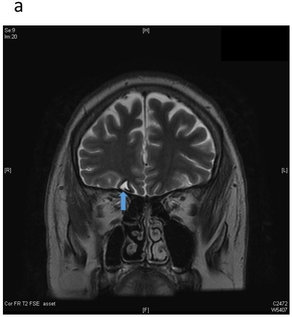
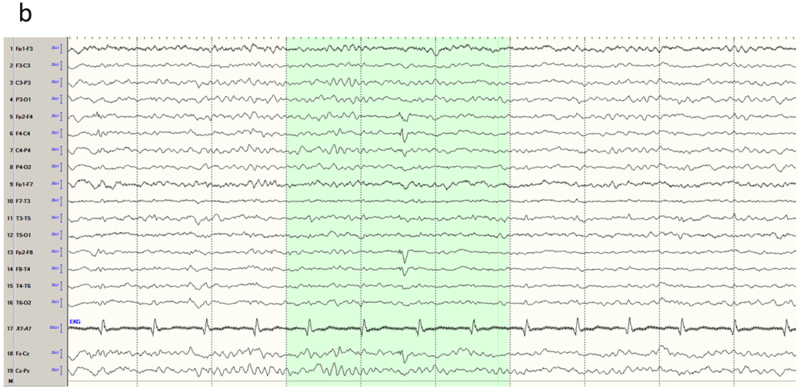
Frontopolar/orbitofrontal epilepsy. a) Coronal T2 sequence through the frontal lobes showing a hemosiderin ring around a small focus of encephalomalacia (arrow) in the right basal frontal region. b) Sleep interictal EEG shows a right frontal spike, maximal (isopotential) at Fp2/F4.
Figure 3.
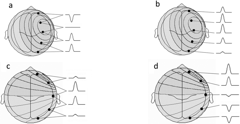
Schema showing behavior of radial and tangent spike dipoles over the lateral frontal surface (courtesy John Ebersole, MD). a-b) Radial spike dipole. Bipolar montage exhibits a phase reversal with isopotential maximum involving two electrode contacts, confirmed by a referential derivation. c-d) Tangential spike dipole. The anterior maximum of the discharge is barely appreciated in the bipolar derivation, and the dipolar character not at all. A referential montage clearly demonstrates the maximum negativity at the end of the chain, in addition to the positive end of the dipole at the opposite end of the chain.
Figure 4.
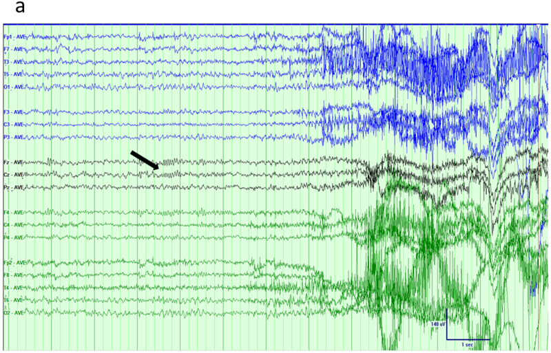
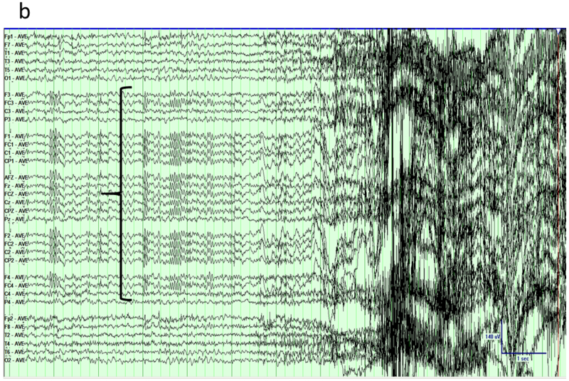
Mesial frontal epilepsy, average reference montage. a) Awake interictal EEG just prior to a seizure shows subtle paroxysmal fast activity over the midline electrodes (arrow). b) Addition of extra electrodes from the 10–10 system visualizes the field of the interictal discharge over multiple contacts (parenthesis).
Figure 5.
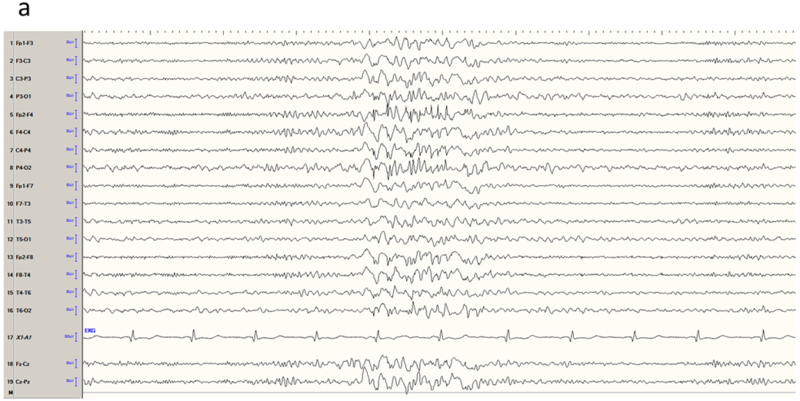
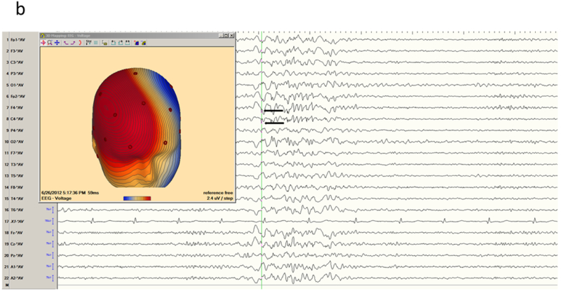
Mesial frontal epilepsy, another example. a) Interictal EEG in longitudinal bipolar montage shows a polyspike-wave burst in a generalized distribution, maximum over the right hemisphere. b) Careful inspection of the sharp components of the discharge (arrows) in average reference suggested positive polarity, confirmed by the voltage field map and locating the generator of the dipole on the medial frontal surface.
Centro-temporal epilepsy
The canonical example of centro-temporal epilepsy is benign childhood epilepsy with centro-temporal spikes (BECTS), one of the most common epilepsy syndromes of childhood. It is an age-related syndrome with a peak age of onset around 8–9 years. Typical semiology is oro-facial motor manifestation and speech disturbance, locating the epileptogenic zone near the lower part of the Rolandic sulcus 21,22. EEG typically shows high amplitude centro-temporal spikes and slow waves which are more frequent in sleep. These spikes usually show a typical horizontal dipole with a maximum negativity over the centro-temporal region and positivity over the frontal regions 23,24. Both bipolar and referential montages can help identifying the area maximally involved. Traditional longitudinal bipolar montages usually show negative phase reversal over the left or right centro-temporal, posterior temporal or parietal electrodes (Figure 6a). Average referential montage helps to identify the maximally involved electrode (Figure 6b); a common reference electrode like Cz is not suitable considering its proximity to the central electrodes C3 or C4 and risk of electrode contamination.
Fig 6.
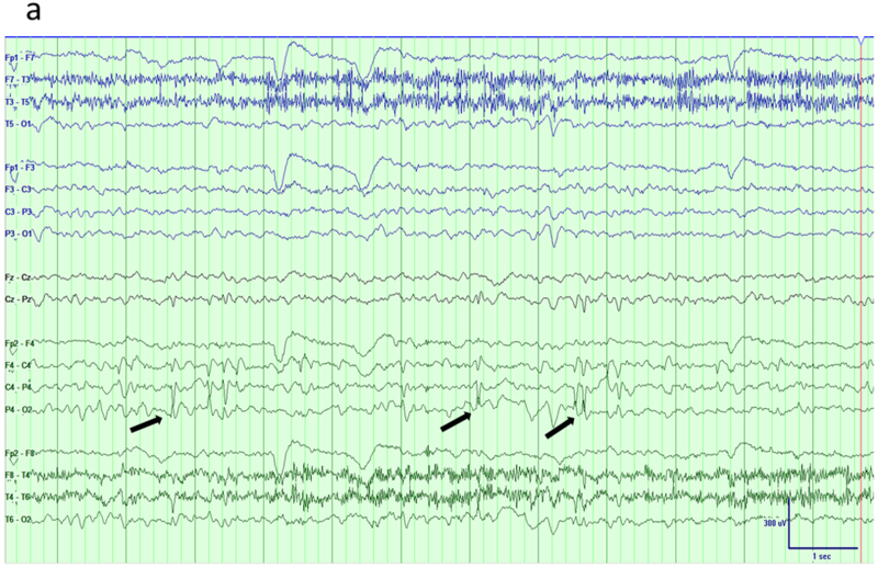
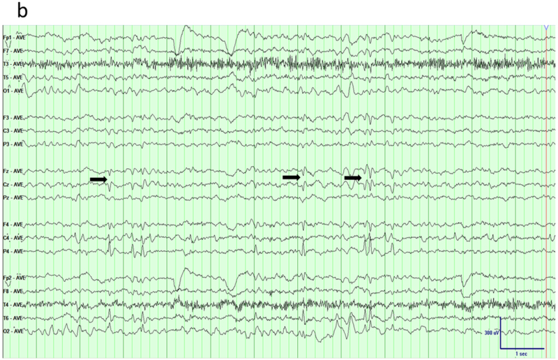
Benign epilepsy with centro-temporal spikes (BECTS). a) Traditional longitudinal bipolar montage shows sharp waves over the right centro-temporo-parietal region (arrows). b) The tangential dipole structure of the generator is brought out in an average reference montage that shows maximum negativity over right posterior temporal/parietal region and positivity (arrows) over the fronto-central areas.
Occipital epilepsies
The term occipital epilepsy is used here to cover variety of different conditions with similar EEG manifestations. These syndromes include genetic age-related syndromes like Panayiotopoulos syndrome or childhood occipital epilepsy of Gastaut as well as symptomatic occipital epilepsy caused by variety of structural abnormalities such as cortical dysplasia or tumor 22. Although all these conditions have occipital paroxysms characterized by spikes or sharp waves, in some these are confined to occipital regions but others may exhibit bilateral occipital, multifocal or generalized discharges too 25,26. An important point to consider when reviewing these EEGs with traditional bipolar montages is that maximum abnormality might lie at the end of the chain with no phase reversal seen (Figure 7a). Although a referential montage, either average or Cz, might help to determine maximum negativity correctly, a modified bipolar montage encircling the head like a halo can bring out phase reversal over the posterior regions (Figure 7b). Montages with similar settings are ‘hatband’ and this particular one used enhance posterior activity called ‘occipital hatband’.
Fig 7.
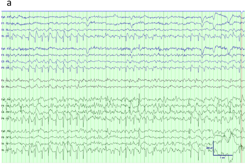
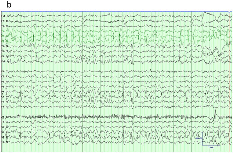
Occipital epilepsy. a) Traditional longitudinal montage reveals frequent spikes over the bi-posterior regions with slightly higher amplitude on the right side. b) A hatband montage (surrounding the head like a halo) reveals phase reversals of epileptiform discharges over bi-occipital regions.
Generalized epilepsies
Generalized epileptiform activity can be seen in variety of conditions. Idiopathic (or genetic) generalized epilepsies (IGE) constitute the majority of this group and can be seen up to 20% of the patients with epilepsy in all age groups. Others include symptomatic generalized epilepsy and focal epilepsies with rapid secondary generalization. Common types of IGE include childhood and juvenile absence epilepsies (CAE and JAE), juvenile myoclonic epilepsy (JME) and other rarer forms of genetic syndromes 27. The inter-ictal hallmark of these syndromes is generalized spike and wave discharges, polyspike-wave discharges and polyspikes. Typically, the frequency of spike and wave discharges is faster in IGE (>2.5 Hz) than symptomatic generalized epilepsy (<2.5 Hz) and background activity is otherwise normal 28,29. Although the bursts are generalized in distribution, the maximum amplitude is generally over the fronto-central regions (Fz, Cz and F3-F4). Some literature suggests that the topography and symmetry is more important than morphology in distinguishing IGE from mimics such as focal epilepsy with a generalized inter-ictal EEG phenotype 30. In addition, sensitivity to hyperventilation and photic stimulation is more common in IGE than focal epilepsies. Different seizure types may occur in patients with IGE but absence is more common in CAE, and generalized tonic-clonic seizures and myoclonic seizures are more common in JME 29. When reviewing EEG in patients with suspected IGE, it is important to consider all the points addressed above. Reviewing the EEG with conventional longitudinal bipolar montages should suffice in the majority of cases. Common average montage or Cz referential montage are usually not helpful because of field contamination. However, since the maximum amplitude is usually fronto-central, single or linked-ear ear reference is sometimes helpful in determining the distribution field. However, for discharges that are very widespread, there would be no suitable reference on the head and a suitable referential montage may not be found (Figures 8a-b).
Figure 8.
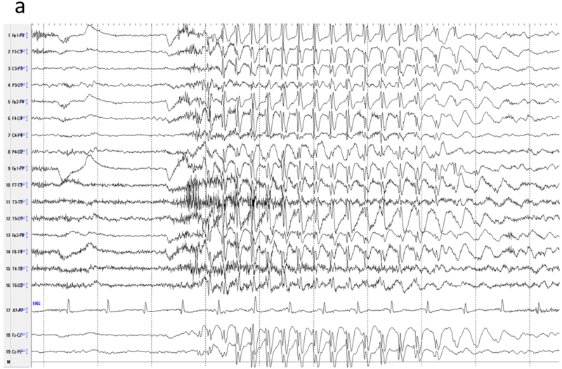
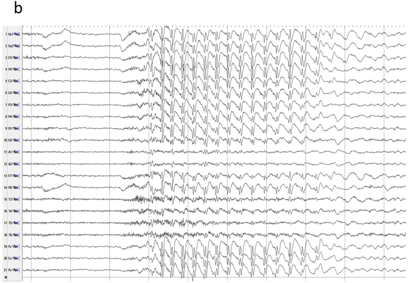
Generalized 3-Hz spike-wave in a child with absence epilepsy. a) High amplitude spike activity is present in most channels. b) A linked-ear referential montage allows comparison of amplitudes to determine the location of maximal activity, which remains widespread in this case. The relative smaller amplitudes in the temporal (T3, T5, T4, T6) derivations are not due to reduced activity at those locations, but an artefact of the proximity of the reference to those channels.
Conclusions
Montages for noninvasive monitoring are best understood in the context of the spatiotemporal behaviour of brain potentials over the head and the generators of common normal and abnormal EEG rhythms. The concept of a dipole and judicious use of bipolar and referential montages bring out the location, extent and polarity of typical EEG generators. In addition to knowledge and experience, a certain flexibility of approach in choosing appropriate bipolar derivations (longitudinal, transverse or hatband) and referential schemes (average, common) is required of the neurophysiologist for optimal interpretation of abnormal waveforms.
Acknowledgements
The authors thank Jayant Acharya, MD, for arranging and inviting us to speak at the conference symposium on which this manuscript is based. EK and GPK acknowledge the encouragement of their colleagues and the efforts of the nurses and technicians at their respective institutions for their role in patient care.
Funding source: GPK acknowledges a NIH career development award (5 K23 NS079900).
Footnotes
Conflicts of interest: None
References
- 1.Nunez PL, Srinivasan R. The physics-EEG interface Electric fields of the brain: The neurophysics of EEG: Oxford University Press; 2006:3–55. [Google Scholar]
- 2.Kasinadhuni AK, Indahlastari A, Chauhan M, Schar M, Mareci TH, Sadleir RJ. Imaging of current flow in the human head during transcranial electrical therapy. Brain Stimul. 2017;10(4):764–772. [DOI] [PMC free article] [PubMed] [Google Scholar]
- 3.Speckman E-J, Elger CE, Gorji A. Neurophysiologic basis of EEG and DC potentials In: Schomer DL, Lopes da Silva FH, eds. Neidermeyer’s electroencephalography. 6th ed. Philadelphia: Lippincott Williams & Wilkins; 2011. [Google Scholar]
- 4.Cooper R, Winter AL, Crow HJ, Grey Walter W. Comparison of subcortical, cortical and scalp activity using chronically indwelling electrodes in man. Electroencephalogr. Clin. Neurophysiol 1965;18:217–228. [DOI] [PubMed] [Google Scholar]
- 5.Tao JX, Ray A, Hawes-Ebersole S, Ebersole JS. Intracranial EEG substrates of scalp EEG interictal spikes. Epilepsia. 2005;46(5):669–676. [DOI] [PubMed] [Google Scholar]
- 6.Gloor P Neuronal generators and the problem of localization in electroencephalography. J Clin Neurophysiol. 1985;2(4):327–354. [DOI] [PubMed] [Google Scholar]
- 7.Scherg M, Ille N, Bornfleth H, Berg P. Advanced tools for digital EEG review: virtual source montages, whole-head mapping, correlation, and phase analysis. J. Clin Neurophysiol. 2002;19(2):91–112. [DOI] [PubMed] [Google Scholar]
- 8.Van CA, Brenner RP. Technical advantages of digital EEG. J. Clin Neurophysiol. 1998;15(6):464–475. [DOI] [PubMed] [Google Scholar]
- 9.Acharya JN, Hani A, Cheek J, Thirumala P, Tsuchida TN. American Clinical Neurophysiology Society Guideline 2: Guidelines for Standard Electrode Position Nomenclature. J. Clin Neurophysiol. 2016;33(4):308–311. [DOI] [PubMed] [Google Scholar]
- 10.Seneviratne U Rational manipulation of digital EEG: pearls and pitfalls. J. Clin Neurophysiol. 2014;31(6):507–516. [DOI] [PubMed] [Google Scholar]
- 11.Lesser RP, Luders H, Dinner DS, Morris H. An introduction to the basic concepts of polarity and localization. J. Clin Neurophysiol. 1985;2(1):45–61. [DOI] [PubMed] [Google Scholar]
- 12.Gordon R, Rzempoluck EJ. Introduction to Laplacian montages. Am. J. Electroneurodiagnostic. Technol. 2004;44(2):98–102. [PubMed] [Google Scholar]
- 13.Ebersole JS, Wade PB. Spike voltage topography identifies two types of frontotemporal epileptic foci. Neurology. 1991;41(9):1425–1433. [DOI] [PubMed] [Google Scholar]
- 14.Kanner AM, Stoub T, Bild S. Nasopharyngeal, anterotemporal and sphenoidal electrodes In: Schomer DL, Lopes da Silva FH, eds. Nidedermeyer’s Electroencephalography. Philadelphia: Lippincott, Williams & Wilkins; 2011:669–676. [Google Scholar]
- 15.Blume WT. The necessity for sphenoidal electrodes in the presurgical evaluation of temporal lobe epilepsy: con position. J. Clin Neurophysiol. 2003;20(5):305–310. [DOI] [PubMed] [Google Scholar]
- 16.Sperling MR, Guina L. The necessity for sphenoidal electrodes in the presurgical evaluation of temporal lobe epilepsy: pro position. J. Clin Neurophysiol. 2003;20(5):299–304. [DOI] [PubMed] [Google Scholar]
- 17.Lee RW, Worrell GA. Dorsolateral frontal lobe epilepsy. J. Clin Neurophysiol. 2012;29(5):379–384. [DOI] [PMC free article] [PubMed] [Google Scholar]
- 18.Unnwongse K, Wehner T, Foldvary-Schaefer N. Mesial frontal lobe epilepsy. J. Clin Neurophysiol. 2012;29(5):371–378. [DOI] [PubMed] [Google Scholar]
- 19.Acharya JN, Hani AJ, Thirumala PD, Tsuchida TN. American Clinical Neurophysiology Society Guideline 3: A Proposal for Standard Montages to Be Used in Clinical EEG. J. Clin Neurophysiol. 2016;33(4):312–316. [DOI] [PubMed] [Google Scholar]
- 20.Gross DW, Dubeau F, Quesney LF, Gotman J. EEG telemetry with closely spaced electrodes in frontal lobe epilepsy. J. Clin Neurophysiol. 2000;17(4):414–418. [DOI] [PubMed] [Google Scholar]
- 21.Huiskamp G, van Der MW, van HA, van NO. High resolution spatio-temporal EEG-MEG analysis of rolandic spikes. J. Clin Neurophysiol. 2004;21(2):84–95. [DOI] [PubMed] [Google Scholar]
- 22.Panayiotopoulos CP, Michael M, Sanders S, Valeta T, Koutroumanidis M. Benign childhood focal epilepsies: assessment of established and newly recognized syndromes. Brain. 2008;131(Pt 9):2264–2286. [DOI] [PubMed] [Google Scholar]
- 23.Medeiros LL, Yasuda C, Schmutzler KM, Guerreiro MM. Rolandic discharges: clinico-neurophysiological correlation. Clin Neurophysiol. 2010;121(10):1740–1743. [DOI] [PubMed] [Google Scholar]
- 24.Sanchez F I, Loddenkemper T Pediatric focal epilepsy syndromes. J. Clin Neurophysiol. 2012;29(5):425–440. [DOI] [PubMed] [Google Scholar]
- 25.Kun LS, Young LS, Kim DW, Soo LD, Chung CK. Occipital lobe epilepsy: clinical characteristics, surgical outcome, and role of diagnostic modalities. Epilepsia. 2005;46(5):688–695. [DOI] [PubMed] [Google Scholar]
- 26.Westmoreland BF. The EEG findings in extratemporal seizures. Epilepsia. 1998;39 Suppl 4:S1–S8. [DOI] [PubMed] [Google Scholar]
- 27.Blume WT. Invited review: clinical and basic neurophysiology of generalised epilepsies. Can. J. Neurol. Sci. 2002;29(1):6–18. [DOI] [PubMed] [Google Scholar]
- 28.Aurlien H, Gjerde IO, Eide GE, Brogger JC, Gilhus NE. Characteristics of generalised epileptiform activity. Clin Neurophysiol. 2009;120(1):3–10. [DOI] [PubMed] [Google Scholar]
- 29.Seneviratne U, Cook M, D’Souza W. The electroencephalogram of idiopathic generalized epilepsy. Epilepsia. 2012;53(2):234–248. [DOI] [PubMed] [Google Scholar]
- 30.Seneviratne U, Cook M, D’Souza W. Consistent topography and amplitude symmetry are more typical than morphology of epileptiform discharges in genetic generalized epilepsy. Clin Neurophysiol. 2016;127(2):1138–1146. [DOI] [PubMed] [Google Scholar]


