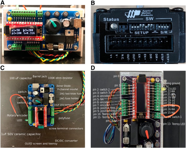
Figure 2.
The syringe pump controller and motor. A, The syringe pump controller. When plugged into a power supply, the OLED screen displays four variables: p1, p2, p3 (indicating the number of steps issued to the motor), and t (fluid delivery time). These can be changed through using the rotary encoder to the right of the OLED screen. B, The motor jumpers are set so that for every 200 pulses issued to the motor, the motor shaft will rotate 360°. Each single pulse or step will rotate 360°/200 = 1.8°. C, Pinout of the controller with the location of various parts on the PCB. D, Pinout details for the teensy microcontroller.

