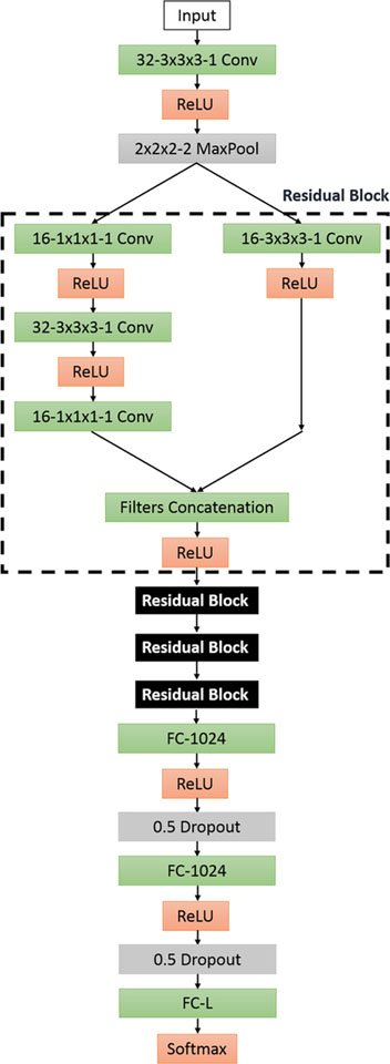
Fig. 2.
RB3D model: each box provides configurations for each layer. The definition of the boxes follows Fig. 1. Four residual blocks are connected, represented by the black boxes. The specific design for a single residual block is shown in the dashlined box

