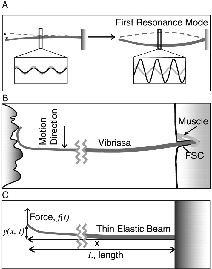
Figure 1.
A diagram of a TEB expressing resonance and the vibrissa sweeping past a surface. A, Left, When stimulated at frequencies lower than the FRF, TEB motion reflects the amplitude of displacement. Right, When driven at its FRF, a TEB demonstrates a significantly larger amplitude motion at its resonance mode. The increase in motion amplitude at this mode is accompanied by a 90° phase shift. Insets: gray, stimulus wave form; black, TEB motion. B, As the vibrissa sweeps past a surface, spatial frequency components in the surface exert a time-varying force on the vibrissa, causing it to deflect at specific temporal frequencies. As with the TEB motion in A, this action should induce resonance in the vibrissa. The vibrissa base is secured in the FSC. C, A diagram of the axes and directions of motion used in the model.

