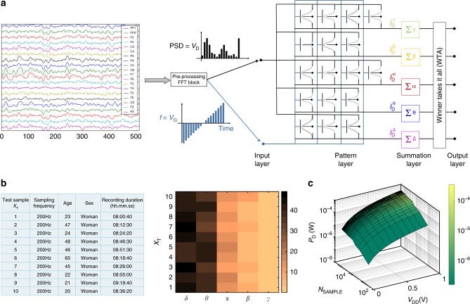
Fig. 5.
PNN Architecture for Brainwave Recognition. a The PNN consists of 4 layers: input, pattern, summation, and output. The amplitude of the FFT data is relayed from the input layer to the pattern layer as drain voltage () of the Gaussian synapses, whereas, the frequency range (0–64 Hz) is mapped to the back-gate voltage () range. The summation layer integrates the current over the full swing of VG from the individual pattern blocks and communicates with the winner-takes-it-all (WTA) circuit that allows the output layer to recognize the brainwave patterns. b Implementation of PNN Architecture: 10 whole-night polysomnographic recordings and the corresponding outcome of the PNN architecture shown using a color map. The PNN recognizes the dominant presence of delta and theta waves in all the sleep samples. c Power Consumption by PNN Architecture: The total power consumption by the PNN as a function of the supply voltage () and sample volume (NSAMPLE). As expected, the power dissipation scales with NSAMPLE and VDD

