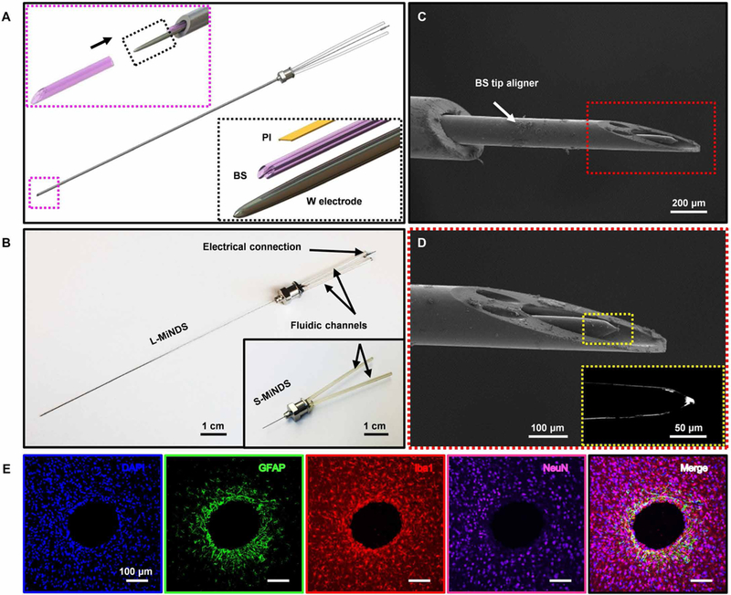
Fig. 1. A miniaturized neural drug delivery system: The MiNDS.

(A) Schematic illustration of a miniaturized neural drug delivery system (MiNDS) with an exploded view of the key device components (right, bottom inset) and with a magnified view of the borosilicate (BS) aligner tip aligning with the key device components in black arrow direction (left, top inset). (B) Image of L-MiNDS and S-MiNDS; electrical connection [tungsten (W) electrode] and the fluidic channels [borosilicate (BS)] are indicated. (C) Scanning electron microscopy (SEM) of the tip of L-MiNDS. (D) Magnified view of a BS aligner tip in the red dashed box in (C). The right inset shows the magnified view of W electrode in the yellow dashed box. (E) Representative confocal fluorescence images of horizontal brain slices showing the stab wound created by implanted MiNDSs, 8 weeks after implantation (n = 5 rats). Immunohistochemical staining for DNA (4′,6-diamidino-2-phenylindole, blue), astrocytes [glial fibrillary acidic protein (GFAP), green], microglia [ionized calcium binding adaptor molecule 1 (Iba1), red], neurons (NeuN, purple), and the merged signals are shown. Results are normalized to intensities 900 to 1100 μm away and averaged into 50-μm bins. The calculated error bars are the SDs.
