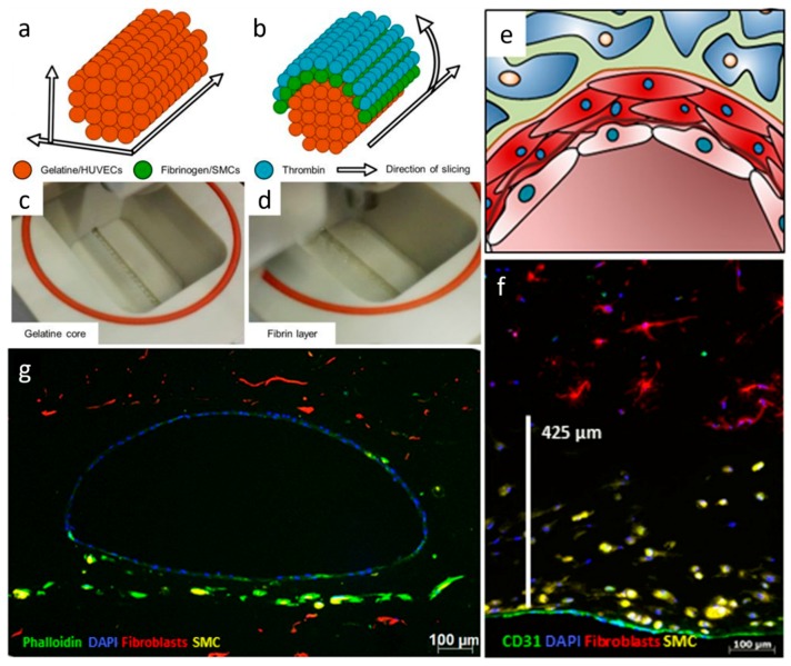
Figure 9.
Printing procedure to manufacture vascular channels in custom-made bioreactors. (a) The gelatine core is deposited by following a printing pattern, which is created by slicing the channels horizontally and calculating the droplets in a grid for each longitudinal section. (b) For the surrounding fibrin layer, the deposition pattern is calculated by slicing the channel lengthwise and defining droplet positions in angular steps around the channel outline of each cross section. (c) To deposit the gelatin core, a single printer head is used at 37 °C. (d) Two printer heads are used, filled with fibrinogen and SMCs alternatingly, as well as thrombin as a crosslinker. (e) Schematic cross section of the channel in close-up shows a single layer of ECs and an additional SMC layer. (f) Combination of SMC layer and the EC layer showing the distribution of SMCs close to the intact channel as a cross section after seven days of flow (CD31 in green, pre-labeled fibroblasts in red, pre-labeled SMCs in yellow, DAPI in blue, 20×). (g) A representative fluorescence microscopy image in cross-section highlights the whole architecture of a multi-layered vessel model after four days of dynamic cultivation; EC are homogenously distributed in the inner part of the lumen, surrounded by fibroblasts and SMCs (phalloidin in green, pre-labeled fibroblasts in red, pre-labeled SMCs in yellow, DAPI in blue, 5×). (a–g) Figure adapted from Schöneberg et al., 2018. Engineering biofunctional in vitro vessel models using a multilayer bioprinting technique. Scientific Reports, Copyright (2018) [21].

