Abstract
Thermoplastic composites based on thermotropic liquid crystalline polymer (LCP) materials are interesting candidates for reinforced composite application due to their promising mechanical performance and potential for recyclability. In combination with a societal push toward the more sustainable use of materials, these properties warrant new interest in this class of composites. Though numerous studies have been performed in the past, a coherent set of design rules for LCP design for the generation of injection-molded reinforced thermoplastic composites is not yet available, likely due to the complex interplay between LCP and matrix components. In this study, we report on the processing of poly(l-lactide) with two different LCPs, at relatively low processing temperatures. The study focuses on critical parameters for the morphological development and mechanical performance of LCP-reinforced composites. The influence of blend composition and the processing conditions, on the mechanical response of the composites, is investigated using rheology, wide-angle X-ray diffraction, mechanical analysis, and microscopy techniques. The study conclusively demonstrates that both the matrix viscosity and viscosity ratio between the dispersed and matrix phase, determine the deformation and breakup of the dispersed LCP droplets during extrusion. In addition, the thermal dependence of the viscosity ratio appears to be a critical parameter for the composite performance after injection molding. For example, during injection molding, stretching and molecular orientation of the LCP phase into highly oriented fibrils are prevented when the viscosity ratio increases rapidly upon cooling. In contrast, melt drawing proves to be a more effective processing route as the extensional flow field stabilizes elongated droplets, independent of the viscosity ratio. Overall, these findings provide valuable insights in the morphological development of LCP-reinforced blends, highlighting the importance of the development of viscoelastic properties as a function of temperature, and provide guidelines for the design of new LCP polymers and their thermoplastic composites.
Introduction
In the 21st century, a societal push toward the more sustainable use of materials has become of paramount importance. Fiber-reinforced composites have excellent mechanical properties, and are used in a wide range of applications. However, the end-of-life options for these materials are often lacking sustainability.1−3 Composites based on main-chain thermotropic liquid crystalline polymers (LCPs) and thermoplastic matrices, produced in one-step during processing, have the potential to provide a sustainable route to reinforced composites. Though the mechanical properties of the composites produced in one-step (in situ) are found to be equivalent to the short glass fiber-reinforced composites,4,5 they are lower than those made from long or continuous fibers, for example carbon fiber. To recall, glass fiber-reinforced composites have a Young’s modulus up to 10 GPa and a tensile strength of 150 MPa,6,7 in contrast to the continuous fiber composites where the fibers themselves have a Young’s modulus and tensile strength exceeding 100 and 1 GPa, respectively.8,9 Though the mechanical properties of the in situ composites is lower than the continuous fiber composites, they are much easier to process—as they make use of the conventional processing steps such as injection molding and extrusion, making them economically attractive and versatile in terms of design and mechanical recycling4,5,10 These properties, in combination with a drive toward sustainability, and advances in LCPs and matrix materials, warrant renewed interest in this type of composites.
Most commercially available LCPs having a high characteristic ratio, are fully aromatic in nature, and have high melting and processing temperatures (>280 °C). This poses a limitation in blending because of the limited thermal stability of most flexible thermoplastic polymers. Therefore, high melting LCPs are normally blended with thermally stable thermoplastic polymers such as PET and PBT.4,10−13 The processing temperatures of LCPs can be suppressed by the inclusion of irregular and/or flexible comonomers along the rigid backbone.14−16 Given the lower thermal requirements of these LCPs, they are useable for the generation of thermoplastic composites based on renewable and thermally labile polymers, including Poly(l-lactide) (PLLA), poly(butylene succinate), and poly(ω-pentadecalactone).17−19
PLLA is a suitable matrix for LCP-reinforced composites, and is among the front-runners of bio-based plastics, produced on a commercial scale, and used in a myriad of applications.20 With a glass transition temperature of approximately 60 °C, PLLA is characterized as a strong, brittle polymer at room temperature. Although it is classified as a semicrystalline polymer, the slow crystallization kinetics often results in amorphous products. It is biocompatible, and under the right conditions, biodegradable. These properties, in combination with strong, biodegradable LCPs21−23 opens up a pathway to reinforced composite materials that are not only reprocessable but also fully biodegradable or even biocompatible.
The reinforcing effect in such LCP/PLLA composites results from the excellent physical and mechanical properties of the LCPs.24−27 In particular, the nematic phase in LCPs invokes low melt viscosities, complex rheological behavior,28−30 and an ease in chain orientation, which, when maintained on cooling, results in products having a high degree of molecular orientation and desired mechanical reinforcement. However, as is reported by Kiss et al., Blizard et al., and Song and Isayev, the mechanical properties of the LCP composites are found to be strongly dependent on the LCP morphology and intern-chain orientation, where both parameters are influenced by the applied processing conditions.4,10−13,16,24,31 For example, during extrusion, the LCP phase is dispersed in the thermoplastic matrix whereas the particle size is governed by the viscosity ratio (LCP viscosity divided by matrix viscosity).32 The generated particles need to be deformed to obtain the desired high interchain orientation. This is generally done by subjecting the blend to shear flow, elongation flow, or a combination thereof. As is reported by Heino and co-workers,32 flow fields that contain a strong elongational component, for example in fiber spinning, are very effective at deforming the particles to yield the desired morphology. In contrast, LCP particle deformation in flow fields with a dominant shear component, for example in injection molding, is not as straightforward as the effective deformation relies on the interplay between the viscosity ratio, the generated particle size, and thermal behavior of both constituents.32−36 Though the aforementioned studies have clearly demonstrated that LCPs can be effective reinforcing fillers, a coherent set of design rules for LCP materials for use in reinforced thermoplastic composites for injection molding is not yet available, likely resulting from the complex interplay between LCP and matrix components.
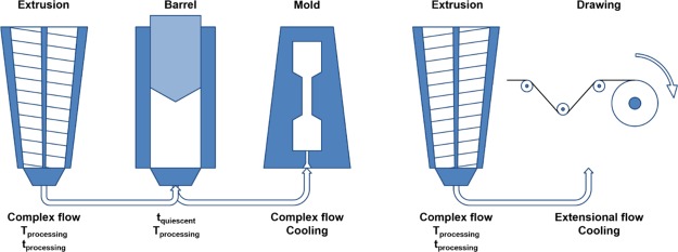
To identify critical LCP properties required for effective LCP reinforcement in shear-flow fields, we report on the influence of the LCP flow behavior and its thermal dependence on the morphological development in LCP/PLLA blends during and after processing. To be more precise, we evaluate the behavior of two different LCPs which can be processed at relatively low temperatures; the first LCP is the commercially available, aromatic copolymer Vectra LCP V400P (LCP-A), whereas the other is an in-house synthesized semiflexible LCP (LCP-B) having both aliphatic and aromatic comonomers and exhibits a significantly enhanced relaxation compared to its aromatic counterpart. Furthermore, the morphological development of the LCP components in the PLLA matrix is assessed during processing via two different processing routes: injection molding route, having a dominant shear-flow component (Figure 1, left) and a melt-drawing route having a predominant elongation-flow field (Figure 1, right). Lastly, the mechanical performance of the generated products is evaluated and correlated to the orientation parameter determined through wide-angle X-ray diffraction. The generated findings are used to identify the structural characteristics required in LCPs for use as reinforced thermoplastic LCP composites made via injection molding.
Figure 1.
Processing routes applied in this study: injection molding (left) and melt drawing (right).
Experimental Section
Materials
Suberic acid, 1,4-diacetoxybenzene, and p-acetoxybenzoic acid were purchased from TCI Europe. The PLLA used in this study was purchased from Corbion (grade L130). The commercial Vectra LCP V400P was purchased from Celanese.
Polymerization Procedure of LCP-B
The synthesis of semiflexible LCP-B was performed based on a previously described procedure: a 1000 mL three-neck glass vessel fitted with a mechanical stirrer. The monomer mixture consisting of p-acetoxybenzoic acid (164.2 g, 911 mmol), suberic acid (158.8 g, 911 mmol), and 1,4-diacetoxybenzene (177.0 g, 911 mmol) was introduced together with 300 mg of Zn(OAc)2 to the round-bottom flask. The monomers were dried overnight in vacuo at 60 °C prior to their usage to eliminate moisture. Furthermore, after the loading of the monomers, the round-bottom flask was iteratively flushed with nitrogen at reduced pressure three times prior to the start of the reaction to minimize oxygen content. Next, a small nitrogen flow was applied to the system and the temperature was increased stepwise to 200 °C. As soon as acetic acid started to be formed, the reaction temperature was gradually increased to 240 °C after which the polymerization was allowed to proceed for 6 h. Next, the reduced pressure was applied to the system for 12 h to build up molecular weight. The final product was isolated from the hot reactor flask in the form of a polymer melt.
Preparation and Processing of PLLA-LCP Blends
PLLA and the LCPs were dried overnight 24 h at 60 °C in vacuo prior to use. Mixtures of polymer pallets were prepared in the following compositions: 0 wt % LCP (i.e., pure PLLA), 10 wt % LCP, and 30 wt % LCP. Next, the mixtures were blended in a DSM Xplore twin-screw micro-extruder with a barrel size of 5 mL. This micro-extruder has a recycle channel and allows for circulation of the material for a given time before guiding the material to the extruder exit using a valve. The materials were mixed for 3 min at 100 rpm at a processing temperature of 240 °C for pure PLLA and LCP-A/PLLA blends and 220 °C for LCP-B/PLLA blends, respectively. After blending, the samples were either processed directly into tapes or transferred into a hot barrel and injection molded into tensile bars. Tapes were generated using a slit die mounted at the extruder outlet (0.5 × 3 mm, produced by DSM Xplore) and a winder (Dienes SD-type). For the generation of the tapes, the extrusion rate was set at 10 rpm and the winder was set at 20 rpm. The tapes were drawn and cooled in air. A DSM Xplore IM 5.5 micro-injection molder was used to produce tensile bars (2 mm × 4 mm × 70 mm, with a gage length of 25 mm). The barrel temperature was set to the previously used processing temperature for the respective composition, while the mold temperature was set to 25 °C.
Material Characterization
The viscoelastic behavior of the blend components was determined in a TA Instruments Discovery HR 2 rheometer with parallel plate geometry (diameter of 25 mm, gap of 1 mm). The samples were loaded at 200 °C and subsequently heated or cooled at a rate of 5 °C min–1 to the required temperature for a frequency sweep at a strain of 1%. The intrinsic relaxation behavior of the LCPs was probed with the same rheometer, at the respective processing temperatures. The specified shear stress was applied to the sample until a strain of at least 300 s.u. was reached (within the plateau region). Next, the deformation was ceased for a given relaxation period after which the stress was reapplied. This second transient was used to acquire information regarding the respective relaxation behavior of the LCPs. The experiments probing the intrinsic relaxation behavior were carried out at the respective processing temperature of each LCP.
The glass transition temperature (Tg) and the peak melting temperature (Tm) were determined by differential scanning calorimetry (DSC) using a TA Instruments Q2000 DSC. The heating and cooling rates of the sample were 10 °C min–1 and measurements were performed under a nitrogen rich atmosphere.
The blend morphology was evaluated via polarized optical microscopy (POM) using an Olympus BX53 microscope (20 or 50 times magnification) equipped with an Olympus DP26 camera and a 530 nm retardation plate. To display the LCP particle morphology created in each processing step, the PLLA phase was dissolved in a mixture of acetone and dichloromethane (3:1 by volume) in which neither of the used LCPs is soluble.
Scanning electron microscopy (SEM) was performed on a Philips XL30 system at an acceleration voltage of 15 kV using 1000 times magnification. The freshly prepared fracture surfaces were attached to the sample holder with conductive carbon tape and subsequently coated with a thin layer of gold.
Tensile testing was performed on a Zwick Z100 tensile on both tapes and tensile bars. The samples were subjected to a constant deformation rate of 5 mm/min, at room temperature. A 10 kN load cell was used for the injection-molded bars. For the tapes, a length of 5 cm was tested via a 200 N load cell.
The molecular orientation of the LCP phase in the pure LCP samples and in the blends was assessed via 2D wide angle X-ray diffraction (WAXD) using a SAXSLAB Ganesha diffractometer using Cu Kα radiation (λ = 0.154 nm). The beam center and θ-range were calibrated via the diffraction pattern of silver behenate. The orientation parameter (S), ⟨P2n(cos φ)⟩d, was calculated from the obtained diffraction patterns via the procedure described by Mitchell and Windle.37 The azimuthal intensity I(φ) at the maximum of the interchain diffraction peak (2θ = 21°) was taken. The orientation parameter ⟨P2n(cos φ)⟩d was then determined from an average of a Legendre polynomial, weighted against the obtained azimuthal intensity scan using eqs 1–3. In this case, only the second order Legendre polynomial was taken into account, ⟨P2n(cos φ)⟩m = −0.5.
| 1 |
 |
2 |
| 3 |
The obtained orientation parameter reflects the contributions of the distribution of the director orientation throughout the bulk polydomain sample and the contributions of the director on a molecular level.38 In short, the orientation parameter reflects the degree of anisotropy of the scattering of polymer chains, while assuming that these chains are infinitely long rigid rods. The values of S vary from 0, corresponding to a random chain orientation similar to the orientation of an isotropic liquid, to unity, corresponding to the perfect alignment of the polymer chains along the orientational axis.
Theoretical Considerations
In general, the morphological development of blends during processing can qualitatively be analyzed within the framework of break-up and coalescence processes. This theory, based on Einstein’s work on the viscosity of dilute suspensions,39,40 was extended to emulsions by Taylor,41,42 whereas Oldroyd43,44 later incorporated the effects of interfaces. Although this framework was originally developed for systems subjected to low deformation rates and for emulsions of Newtonian liquids, it has also provided insight in complex systems involving viscoelastic dispersed and matrix phases.45−48 Therefore, these theoretical concepts are used to describe the morphological development during the processing of the thermoplastic polymers in this study. Note, buoyancy is not taken into account in this theory, which is considered a reasonable assumption for polymer melts with high viscosities.
The deformation of a spherical liquid droplet in a matrix can be described mainly by two dimensionless numbers: the capillary number (κ, eq 4) and the viscosity ratio (λ, eq 5).
| 4 |
| 5 |
In these equations, γ̇ represents the applied shear rate, d represents the droplet diameter, ν12 represents the interfacial tension, and η represents the viscosity of either the dispersed or the matrix phase. The capillary number describes the balance of hydrodynamic and surface forces acting on a dispersed droplet with a specific diameter. The viscosity ratio is a measure of how effectively such a droplet can be deformed by the matrix.
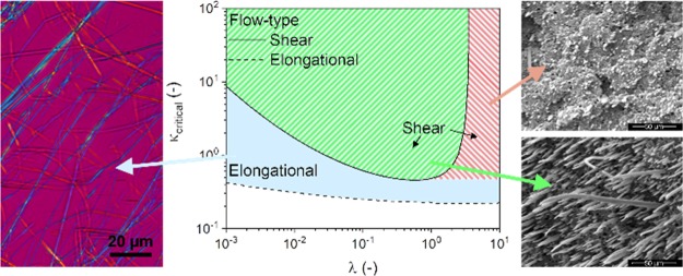
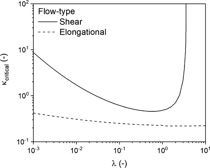
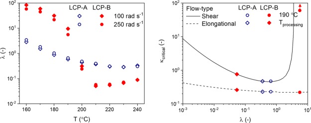
The type of flow field to which an emulsion is subjected has a strong influence on the behavior of droplets, as was shown by Tomotika.49 In order to allow droplet deformation, the capillary number needs to be larger than a certain value: the critical capillary number (κcritical, eq 6). As the droplet stretches, its diameter and correspondingly the capillary number, decreases. When the capillary number of a droplet equals the critical value, the hydrodynamic forces no longer stabilize the deformed droplet and breakup can occur. Values for κcritical in different types of flow fields have been experimentally determined45,50 as a function of λ (Figure 2). The constants c1–c5 in eq 6 are flow-type specific and are provided in the Supporting Information. Based on Figure 2, one can deduce that the application of shear flow is not sufficient to disperse droplets with a high viscosity ratio (λ > 3.8). In this scenario, the timescale for deformation becomes so large that the droplets simply rotate. In contrast, an extensional flow field can deform droplets regardless of the viscosity ratio,51,52 and is in general more effective in deforming and breaking up of droplets then the shear flow.
| 6 |
| 7 |
Figure 2.
Critical capillary number (κcritical) as a function of viscosity ratio (λ).
The behavior of a droplet in a matrix can be described by the reduced capillary number, κ* (eq 7), being the ratio of the capillary number κ and the critical capillary number κcritical. Four regimes in droplet behavior can be identified with respect to κ*.53 Regime 1 involves the scenario where κ* < 0.1, a regime where no deformation of droplets occurs in a matrix. Regime 2 corresponds to 0.1 > κ* > 1, corresponding to the deformation of droplets without break-up. Regime 3, occurring when 1 > κ* > 4 corresponds to the deformation of droplets and their splitting into primary droplets. Lastly, affine droplet deformation into stable filaments occurs in regime 4, when κ* > 4. To illustrate, a large droplet, having a κ* corresponding to regime 3, will deform and break up when subjected to a flow field, effectively decreasing its diameter and thus its capillary number κ. This deformation and breakup process will continue, effectively reducing both the capillary number κ and reduced capillary number, κ*. This process continues until κ* becomes smaller than 1, effectively reaching regime 1 or regime 2 where no further breakup occurs.
In order for the droplets to behave as described above, the forces involved need to provide a certain amount of work. As a result, the scale of the deformation and the time over which it occurs are relevant for the behavior of droplets. The timescale associated with the complete breakup of a droplet (t*, eq 8) was determined experimentally50,54
| 8 |
The theoretical approach so far describes the behavior of individual droplets, but large amounts of droplets are present in real systems. These droplets can collide, and in case the fluid matrix separating the particles is drained, the droplets can coalesce again forming larger droplets. Because of the coalescence, the observed droplet size is generally larger than that predicted from theories that only account for particle breakup (with very dilute systems as exception).55 Many parameters that promote breakup, influence the coalescence of droplets in a similar fashion: higher shear rates and a lower viscosity ratio tend to accelerate coalescence.56 The number of droplets present per volume, the draining conditions, and the timescale govern the overall coalescence process. More importantly, the opposing effects of the breakup and coalescence determine the dynamic equilibrium state for a constant flow field that is applied on a sufficient timescale. Under such conditions, though the system remains dynamic, the overall morphology of the blend remains constant.
The theoretical framework described above was initially developed to describe Newtonian systems. However, the rise of polymer blending, which involves viscoelastic components, required information on the breakup and deformation behavior of droplets in non-Newtonian systems. Studies have been carried out to determine the influence of viscoelasticity on the equilibrium blend morphology and the development of the morphology in case either the droplet phase or the matrix phase, or both are viscoelastic.30,45,47 Generally, it was found that increased elastic contributions hindered the breakup and led to a larger equilibrium droplet diameter. To estimate the importance of viscoelasticity in the used blends, the Weissenberg number (Wi, eq 9) was calculated for the PLLA matrix at the processing temperature.
| 9 |
λrelaxation indicates the relaxation time of the melt, for which the reciprocal value of the crossover frequency was taken (mastercurve is provided in the Supporting Information), and γ̇ indicates the applied shear rate (a value of 300 s–1 was taken). Values for Wi vary from 0.279 to 0.129 for processing temperatures between 220 and 240 °C, respectively, indicating that under these conditions the response is mainly viscous, but that the elastic component does play a significant role. This would suggest that the experimental particle size is likely to be larger than that predicted by the theory described above. Irrespective of this, as the development of the morphology is governed by deformation, breakup, and coalescence processes, this theoretical framework will be a valuable tool to describe the morphological behavior of the blends evaluated in this study. For further information on the topic of polymer blends and their morphology the authors refer to an overview on the topic by Kamal,57 and to works implementing this framework in extrusion (Shi, Utracki et al.53,55,56,58) and fiber spinning (Song and Isayev31).
Results and Discussion
Thermal Behavior and Viscoelastic Response of the Blend Constituents
Prior to evaluating the effect of the processing conditions on the blend morphology and the resulting mechanical properties, the thermal and rheological behavior of the individual components was investigated. In this study, two LCPs with low processing temperatures were evaluated as reinforcing fillers for PLLA. As mentioned in the experimental section, a fully aromatic copolymer, Vectra LCP V400P (LCP-A), was used and a semiflexible LCP was developed in-house with 33 mol % of suberic acid as nonaromatic units (LCP-B). The behavior of all used polymers, as observed in DSC at a heating and cooling rate of 10 °C min–1, is shown in Figure 3. The heating run of the semiflexible LCP-B shows a broad glass transition temperature (Tg) around 50 °C, followed by a broad melting peak with a maximum at 185 °C. The broadness of the melting peak is expected to originate from the various possible crystalline aromatic sequences. When heated beyond 200 °C the LCP-B exhibits a stable nematic phase until degradation sets in well above 300 °C, as is reported in earlier work.59 LCP-A is a fully aromatic copolymer, which does not exhibit extensive formation of nonperiodic layer crystallites. From Figure 3 it can be observed that the rigid backbone leads to a high Tg of around 110 °C and a very small melting endotherm between 200 and 230 °C. Lastly, the used PLLA grade crystallizes slowly, as indicated by the incomplete crystallization during cooling and the presence of a large cold crystallization peak during heating. Additionally, PLLA exhibits a Tg of around 60 °C and a peak melting temperature of 175 °C. Overall, this data suggests that the blending of PLLA with LCP-B can be performed at 220 °C as LCP-B is fully molten at this temperature and resides in the nematic phase. Similarly, blending LCP-A in the nematic phase with PLLA and would require a temperature of 240 °C.
Figure 3.
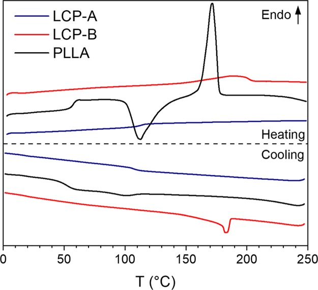
DSC thermograms of the components used in this study, taken at a heating and cooling rate of 10 °C min–1 (endo up).
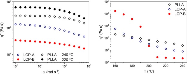
Figure 4 (left) shows the complex viscosity as a function of angular frequency for both LCPs and the PLLA at the previously mentioned processing temperatures. As expected for linear polymers, all materials show shear thinning behavior at ω > 50 rad s–1. A considerable difference in viscosity between the two LCPs is observed over the measured frequency range, indicating that the viscosity ratios for the LCP-A/PLLA and LCP-B/PLLA blends are different under the used processing conditions. In drawing and injection molding, the blends are simultaneously deformed and cooled; therefore, the viscosity of the components as a function of temperature is highly relevant. Figure 4 (right) shows the dependency of the complex viscosity over temperature at ω = 100 rad s–1. One can observe that PLLA is considerably more viscous than both LCP polymers above 200 °C, that is, under the used processing conditions. During cooling, the complex viscosity increases for all components. The viscosity of LCP-A surpasses that of PLLA around 180 °C, likely resulting from the higher Tg of LCP-A compared to PLLA. For LCP-B, crystallization proceeds during cooling below 200 °C, resulting in a steep increase in viscosity during further cooling. One can imagine that when blended, the differences in thermal behavior of the individual components will affect the blend morphology during processing; a change in the viscosity ratio occurs during cooling, affecting the (reduced) capillary number, and the particle deformation and breakup processes and thus the blend morphology.
Figure 4.
(Left) Complex viscosity (η*) as a function of frequency (ω) for PLLA, LCP-A, and LCP-B determined at the extrusion temperature of the blend components. (Right) Complex viscosity of the same components as a function of temperature, taken at a frequency of 100 rad s–1.
Effect of Blend Extrusion on the LCP Particle Morphology
PLLA and both LCPs were extruded for 3 min at 100 rpm to disperse the LCP phase in the PLLA matrix. As mentioned earlier, processing temperatures for blends containing LCP-B were 220 °C, whereas blends with LCP-A were extruded at 240 °C. As is depicted in Figure 5, the viscosity ratios at the processing temperature for both blends are relatively constant with respect to the angular frequency. Though the shear rates can be higher during extrusion, we expect that the viscosity ratio remains constant under the used conditions. However, one can observe that the viscosity ratio for the LCP-A/PLLA blends is roughly a factor 10 larger compared to the LCP-B/PLLA blends. Despite this difference in the viscosity ratio, the calculated critical capillary numbers for systems with these viscosity ratios are very similar, with κcritical (shear) 0.5–0.75 and κcritical (elongation) ≈ 0.25. In order to make an estimate for the actual value of the capillary number, a calculation was done based on a hypothetical but representative case of a droplet in a matrix with d = 100 μm, ηmatrix = 100 Pa s, γ̇ = 100 s–1, and ν12 = 10 mN m–1. These assumptions yield a κ value of 100. Consecutively, for both blends κcritical < 1, regardless of the flow type, yielding a κ* well over 100. Based on this estimate, LCP droplets with a diameter in the micrometer range are effectively deformed by the flow field and are expected to stretch into stable filaments already during extrusion. Similarly, the timescale of the droplet breakup can be estimated using λ = 0.5 and κ* = 100 (a case similar to a large droplet in a LCP-A/PLLA blend), yielding a t* of 4.1 s. This value is considerably shorter than the extrusion time, confirming that the droplet breakup occurs during extrusion. In this study we considered both blends having comparable interfacial tension. As a result, in the comparative study, no significant effects on the mechanical response are expected from the interfacial tension: we recall that the interfacial tension for polymer–polymer systems is generally in the range of 1–10 mN·m–1, where changes in the temperature and limited variations of the chemical composition only result in minor deviations of the interfacial tension.60−62
Figure 5.
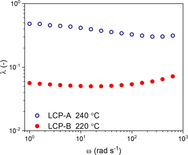
Viscosity ratio (λ) vs frequency (ω) as calculated for both LCP/PLLA blends at the respective processing temperatures.
The previous estimations suggest that the dispersion of the LCP occurs readily in a shear flow field as particles subsequently stretch and break up. However, the flow field applied in extrusion is rather complex as it comprises a combination of elongational and shear flow fields that vary along the extruder positions. As a result, the variation in the flow field with the position of the fluid element in the extruder hinders the formation of stable LCP filaments and promotes breakup instead. As extrusion time increases, the particle size decreases, until a dynamic equilibrium is achieved where a number of distinct types of LCP droplets are expected: (1) large spherical droplets; these are the result of droplets that have not been broken up or have been formed because of coalescence events and are expected to deform and break up in the future. (2) Deformed large droplets; due to their initial large diameter, the flow field is in the process of stretching them into filaments that are stable or later break up into two droplets. (3) Fibrils which originate from larger droplets; they have not been stretched so far as to become instable and break up. (4) Small, spherical droplets which are the product of breakup events; these droplets have a low value of κ* due to their small size and are not deformed further by the imposed flow fields.
Large LCP fibrils are expected to be rare in the barrel of the extruder, as the varying flow field is likely to cause instability. Therefore, the droplet morphology is expected to consist mostly of types 1, 2, and 4. However, as the molten blend exits the extruder, the barrel tapers into a narrower channel, creating a zone with a dominant extensional flow profile. In this zone, droplets with high aspect ratios (type 3) are expected to be the dominant morphology.
When relating this to the LCP-B/PLLA blends, we expect a decreased average droplet diameter compared to the LCP-A/PLLA blends. To recall, the blends containing LCP-B are processed at 220 °C, leading to a higher ηmatrix and κ, and thus more effective droplet deformation and breakup. Additionally, the viscosity ratio for these blends is lower compared to that of the LCP-B/PLLA blends, reducing the timescale for the breakup. As such, the dynamic equilibrium between the breakup and coalescence will be pushed into the direction of smaller particles. Regardless of which LCP component was used in the blend, the overall droplet size increased with the volume fraction of LCP, as a higher number of droplets of a given size is required at a higher volume fraction. This leads to a higher collision frequency, pushing the dynamic equilibrium toward larger droplets.
To verify the accuracy of these predictions, the extrudates of both LCP-A/PLLA and LCP-B/PLLA blends containing 10 and 30 wt % LCP were analyzed in POM (Figure 6). In order to study the LCP morphology, the PLLA was dissolved in a mixture of acetone and dichloromethane (1:3 by volume). Overall, the observed LCP particle morphologies agree rather well with the expectations; the average particle size is smaller for blends containing LCP-B and the particle size increases with increasing LCP content for both blends. Furthermore, stretched LCP fibrils are detected combined with two populations of spherical LCP particles with a clear separation in size. In the 10 wt % LCP-B/PLLA blend, elongated structures are largely absent. The reason for that might be twofold: the low average diameter in this blend, in combination with a quicker expected timescale for the breakup, has led to breakup on timescales shorter than that of the quenching; these structures are destroyed largely as the matrix is dissolved. Additionally, the shape of most of the fibrillar structures in the other samples is not truly fibrillar, instead the fibrils contain thick, droplet-like segments, separated by thinner, seemingly stretched segments. Their appearance suggests that the filaments were not stable and in the process of breaking up. This can be attributed to the lack of stress as the strand exits the die in combination with the timescale of quenching. Nevertheless, the observed LCP particle morphologies are in excellent agreement with the morphology expected from the theory.
Figure 6.
LCP particle morphology of blend extrudates. From left to right: 10 wt % LCP-A in PLLA, 30 wt % LCP-A in PLLA, 10 wt % LCP-B in PLLA, and 30 wt % LCP-B in PLLA. Note, the PLLA matrix was dissolved in a 1:3 mixture of acetone/dichloromethane prior to capturing the LCP particle image, causing the formation of agglomerates of individual particles.
LCP Particle and Interchain Relaxation during Isothermal Conditions
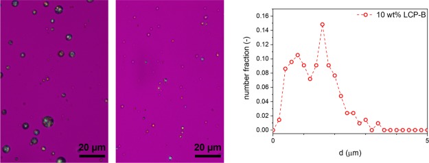
Prior to injection molding of the sample, the molten blend is transferred into a preheated barrel, where it is maintained under quiescent and isothermal conditions at a high temperature for some time (in the order of 10 s to 1 min). During this isotherm, the LCP droplets experience no stresses and deformed LCP particles will either contract or break up into multiple droplets. The timescale for the breakup will be shorter in LCP-B/PLLA blends resulting from their decreased viscosity ratio compared to LCP-A/PLLA blends. Additionally, combined with the intrinsic relaxation of LCP upon the cessation of flow, the decreasing average aspect ratio of the particles leads to a rapid decrease in the interchain orientation of the LCP within the particles. As a result, after the isotherm, an LCP particle morphology consisting of only spherical droplets of various sizes is expected. Indeed, this seems to be the scenario, as is visible from the optical micrographs in Figure 7. The presence of only spherical LCP particles confirms full relaxation of the oriented LCP particles, during the time the blend resides in the barrel. Furthermore, as observed earlier, two populations of spherical droplets with different diameters are present, and the expected differences in particle morphology resulting from the LCP concentration difference remain clearly visible. The minimum particle size was considerably larger than the estimated theoretical minimum value, as is expected for blends of viscoelastic materials.57 A more elaborate analysis of the particle morphology is available in the Supporting Information.
Figure 7.
LCP particle morphology of extruded strands after heating to the processing temperature for 1 min. From left to right: 10 wt % LCP-A in PLLA, 10 wt % LCP-B in PLLA, particle size distribution of 10 wt % LCP-B in PLLA. Note, the PLLA matrix was dissolved in a 1:3 mixture of acetone/dichloromethane prior to capturing the LCP particle image.
In addition to the loss of the interchain orientation of LCP melts due to changes in blend morphology, the interchain orientation in LCPs is known to decrease upon the cessation of flow. In order to estimate the timescale of this process, the intrinsic relaxation behavior of the LCPs has been evaluated. In previous works, under conditions where the LCP viscosity is constant as a function of shear rate, we have shown that the relaxation of LCPs scales linearly with the applied shear rate and occurs via a two-step mechanism.63 Initially a fast contraction of the domain texture occurs, followed by a slower coalescence of the liquid crystalline domains. As a result, LCP melts subjected to a higher shear stress display enhanced interchain relaxation rates.63,64
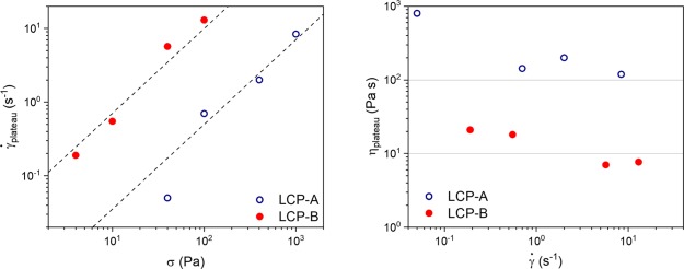
The shear response of LCPs typically shows a minimum in viscosity at low strain, followed by a maximum, and at sufficiently large strains, a plateau is reached. These phenomena are correlated to the development of the interchain orientation and the domain texture of the LCP, and can be used as an indicator for the relaxation behavior.65 In order to confirm that the experiments conducted on both LCPs are performed in the regime where the LCP plateau viscosity is constant as a function of shear rate,66 the LCPs were subjected to a constant shear stress until a plateau value was reached. Figure 8 (left) shows the plateau shear rate as a function of the applied shear stress. The observed shear rates seem to follow a slope of 1.15, marked by the dotted lines, which is close to the expected slope of 1. The dependency of viscosity on shear rate is presented in Figure 8 (right) and shows that the viscosity of LCP-A is roughly a factor 10 larger compared to that of LCP-B over the measured range of shear rates. Additionally, the plateau viscosity is indeed almost constant with respect to the shear rate, indicating that both LCPs are indeed in the expected regime. The only exception is the measurement of LCP-A at the lowest applied shear stress, which has a considerably higher viscosity.
Figure 8.
Steady state shear rate vs applied shear stress for both LCPs (left). Steady state viscosity vs shear rate for both LCPs (right). Data was collected at the respective extrusion temperatures of the LCP/PLLA blends.
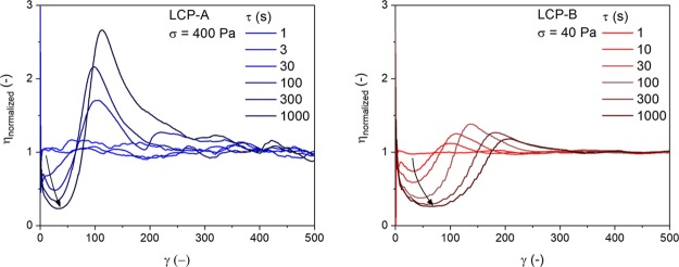
To identify the rate of the domain coalescence process, which is linked to the decreasing the interchain orientation, the samples were sheared at a constant shear stress until the equilibrium state was reached (at least 400 s.u.). Next, the deformation was stopped and the molten LCP was subjected to a relaxation time τ, varying from 1 to 1000 s. The evolution of the viscosity as a function of shear strain after the reapplication of shear is shown in Figure 9. In both LCPs, for short relaxation times (τ = 1 s), the viscosity increases at very low strains as the shear stress is reapplied, and reaches a constant value almost immediately. The minimum and maximum, characteristic for the evolution of the domain texture and interchain orientation, are completely absent, indicating that, on this timescale, relaxation has a negligible influence on the polydomain texture of the LCPs and domain coalescence has not progressed significantly. As the relaxation time increases, the characteristic minimum and maximum become more significant, indicating further progression of the textural relaxation. Because the evolution of the orientation parameter and the texture are closely related, these experiments indirectly give information with respect to the interchain orientation: a lack of textural relaxation indicates that the interchain orientation is maintained, whereas strong textural relaxation indicates a loss of the interchain orientation.
Figure 9.
Transient behavior of both LCPs following different relaxation periods. Data was collected at the respective extrusion temperatures of the LCP/PLLA blends.
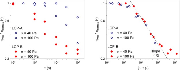
Figure 10 (left) shows the evolution textural relaxation after different stresses have been applied to both LCP-B and LCP-A. The ratio of the viscosity of the minimum with respect to the plateau was used to characterize the textural relaxation. Lower values correspond to a texture closer to the quiescent “mono-domain” texture, hence further progression of the textural relaxation and thus a decrease in the interchain orientation. Overall, we observe that, at similar shear stresses, the LCP texture relaxes roughly 10 times faster in LCP-B compared to LCP-A. This large difference in relaxation time therefore seems to be related to the lower viscosity and the more flexible backbone of the aromatic–aliphatic LCP-B. Furthermore, for both LCPs, we observe that the textural relaxation slows down and levels off at long timescales, which would correspond to the LCPs approaching the quiescent “mono-domain” texture. As expected, the application of higher stresses results in faster relaxation, originating from the increase in the applied shear rate. Figure 10 (right) shows the same relaxation experiments, but with the relaxation time normalized for the applied shear rate, effectively compensating for differences in viscosity. It is noteworthy that the normalized data from the different experiments falls on the same curve. The decrease in the ratio consistently followed a slope of -1/3 for both LCPs over the range of applied shear stresses. Overall, this data confirms that the LCP texture and interchain relaxation is significantly enhanced after the application of increasing shear stresses and with decreasing the LCP viscosity. Note, the magnitude of the applied shear stresses in these experiments needs to be considered: it is considerably lower than what one would expect in the actual processing of blends and therefore extrapolation is required to estimate the effect of relaxation during the quiescent period in the barrel. A 10- to 100-fold increase in shear stress would shift the timescales for textural relaxation well within the 10 second range, the residence time of the molten blend in the barrel. In combination with the breakup and retraction of fibrils due to a lack of stabilizing stresses, no residual interchain orientation of the LCPs is expected in any of the blends at this stage in the processing.
Figure 10.
Textural relaxation of the LCPs as a function of relaxation time (left), normalized with the steady state shear rate (right). Data was collected at the respective extrusion temperatures of the LCP/PLLA blends.
Injection Molding
Subsequently to its residence in the heated barrel, the molten blend is pushed out of the barrel into a cold, dogbone-shaped mold. In this processing step the material is subjected to high cooling rates in combination with a complex flow field and high deformation rates. As the pressure is applied, the molten blend is forced out of the barrel through a tapered die into the mold. Because of the onset of deformation, the collision frequency increases tremendously and coalescence can occur again; droplets are effectively deformed into fibrils as the blend is forced out of the barrel. As the mold is dogbone-shaped, the resulting flow field is complex and dependent on the actual position of the fluid element. Nevertheless, it is generally accepted that the injection-molded polymer next to the wall of the mold is unable to flow and is subject to high shear rates and shear stress. In contrast, when moving further away from the wall of the mold, the polymers are subject to lowered shear stresses and are able to flow. Typically, a shear layer is formed close to the mold wall in injection molding as a result of both the high shear rate and cooling rate. Because of this rapid cooling, the PLLA chains residing close to the wall are oriented along the flow direction and are immediately quenched to temperatures below Tg, effectively preventing their crystallization. A similar deformation scenario is expected for the dispersed LCP droplets, where the shear rate close to the wall results in deformation and rapid molecular orientation during the cooling process. However, due to the flow limitations at the wall, the LCP morphology close to the mold wall is expected to be ribbon like.
Toward the core of the bar, the molten blend experiences a decreasing cooling rate. The blend that is not in contact with the mold walls will change in viscosity during this cooling process, effectively resulting in an increase in the viscosity ratio. Figure 11 (left) shows the expected change in the viscosity ratio, as is evaluated using plate–plate rheology. In general, we observe that the viscosity ratio gradually increases from approximately 0.5 to 3 in LCP-A/PLLA blends as the temperature range drops from the processing temperature to 160 °C. In contrast, LCP-B, crystallizes rapidly as the material is cooled, effectively resulting in an increase in the viscosity ratio from 0.06 to values close to 100 as the temperature decreases from the processing temperature to 160 °C.
Figure 11.
Evolution of the viscosity ratio for the two different LCP/PLLA blends with temperature (left). The effect of cooling on the critical capillary number for the LCP/PLLA blends (right).
The implications of the changes in the viscosity ratio for κcritical are depicted in Figure 11 (right). In the case of LCP-A/PLLA blends, κcritical remains between 0.2 and 0.5, depending on the flow field (at least during cooling to 190 °C), correspondingly causing values for κ* to remain high. To recall, under these conditions, particle deformation into stable filaments is favored; the extended filaments are stabilized quite well by shear stresses during cooling. In contrast, in the case of LCP-B, the viscosity ratio increases dramatically over the temperature range between 200 and 160 °C. This causes κcritical to rise drastically and κ* to drop significantly. Consequentially, LCP droplets cannot be deformed effectively by a shear-type flow field anymore, resulting in a significantly decreased droplet deformation and thus a lowered degree of the interchain orientation of the LCP-B particles.
Combining the LCP particle morphology prior to injection molding (Figure 7) with the difference in deformation behavior of the LCP particles based on the changes in κcritical during cooling (Figure 11, right) allows for a rough prediction of the final LCP morphology after injection molding. LCP-A/PLLA blends are expected to yield relatively thick LCP filaments with very high aspect ratios, owing from the relatively large LCP droplet size prior to injection molding. In contrast, the LCP-B/PLLA blends are expected to contain significantly thinner LCP fibrils with low aspect ratios, owing to their finer starting morphology and the lower stability of fibrils due to the rapid increase in the viscosity ratio upon crystallization. Furthermore, in both blends, the small droplets that were initially present are, due to the tendency of small droplets to rotate rather than deform in shear, likely to be unaffected by the imposed flow fields. For this reason, in addition to the oriented LCP particles, a distribution of small LCP droplets can be expected.
The LCP particle morphology and the interchain orientation of the LCP phase after injection molding were analyzed using SEM and WAXD (Figure 12, for blends containing 30 wt % LCP). The analysis of the blends containing 10% LCP are provided in Figure S7 in the Supporting Information. Indeed, as expected, both samples contain clear shear layers (left row, Figure 12), although the expected ribbon-like particle morphology is only clearly observed for LCP-A/PLLA composites. Toward the core of the sample, we observe that LCP-A indeed is present as thick elongated fibrils. Indeed, the LCP-B particles do not seem to be as elongated as is the case for LCP-A, but instead persist as short fibrils or nodules.
Figure 12.
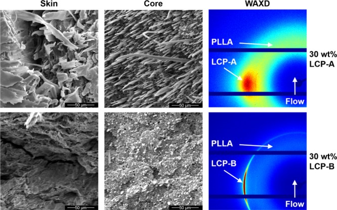
Microstructure of injection-molded samples: SEM-images of sample skin (left), SEM-images of sample core (middle), diffractograms (right).
The 2D-WAXD diffraction patterns of the produced bars show an amorphous halo in the lower q-range, corresponding to the presence of amorphous PLLA throughout the sample. The LCP components are detected at a slightly higher q-range and are visibly oriented, indicated by the presence of arcs of the interchain diffraction signals. Interestingly, the diffraction of LCP-B shows an isotropic peak superimposed on the arc, suggesting an inhomogeneous degree of orientation throughout the sample. Such diffraction behavior is related to the spatial variation in the LCP morphology in the sample; LCP-B residing in the shear layer will exhibit a high interchain orientation, whereas the small nodules in the core of the sample are expected to give rise to isotropic scattering. Such behavior is not observed in LCP-A/PLLA samples, confirming that indeed the LCP-A has a high interchain orientation, both in the shear layer and in the core of the bar.
Melt Drawing
To prepare melt-drawn PLLA/LCP blends, the LCP and PLLA pellets are fed into the twin-screw extruder, and the same extrusion conditions were applied as for the injection molding process. Contrary to the injection molding route, where the blends are extruded into a barrel to remain quiescent for a time after extrusion, the molten blend is pushed through a slit die, and the tape is simultaneously cooled by air and stretched by a rotating roll. In other words, the blend is continuously subjected to an extensional flow field after it leaves the extruder, until it solidifies as a result from the air-cooling. Under such conditions, extended LCP fibrils are stabilized in all blend compositions during the entire drawing process, as is reported by Song and Isayev.31 Indeed, such behavior is expected for both LCP-A- and LCP-B-based blends, as the sudden increase in the viscosity ratio upon the crystallization of LCP-B does not lead to a drastic increase in κcritical in an extensional flow field (Figure 11, right). Though the presence of elongated fibrils is expected in both blends, the possibility of fibril breakup cannot be excluded; because of the continuous drawing, the fibrils are continuously decreasing in diameter and therefore subject to lower stresses, possibly causing instability and breakup. Breakup in this fashion would result in the generation of a large number of small droplets.55 To recall, such small droplets with a diameter in the range of a few micrometers, are not as effectively deformed by the flow field and might therefore persist. Nevertheless, such droplets might disappear due to the coalescence with other droplets or fibrils in the deforming melt.
In addition, the high cooling rate that the tapes encounter stabilizes the fibrillar LCP morphology and allows its features to be frozen in a highly stretched state before relaxation can occur. Figure 13 shows the morphology of the LCP fibrils in the obtained tapes. Indeed, as expected, the dominant species are fibrils with a high aspect ratio (>100), though a small amount of droplets is detected as well. The homogeneous coloring of the fibrils in the optical micrographs indicates that the chains inside the fibrils are all oriented in the same direction, thus suggesting a high degree of interchain orientation. Indeed, the high degree of interchain orientation is also observed from WAXD, as is shown in Figures S8 of the Supporting Information. Again, as a result of the starting morphology after extrusion (Figure 7), LCP-B tapes to contain thinner LCP fibrils compared to LCP-A/PLLA tapes. A similar trend is observed between blends having 30% LCP and 10% LCP, again resulting from the difference in the LCP particle morphology generated in the extrusion step. Overall, this data confirms that the limitations in LCP particle orientation by the shear components in the flow fields present in injection molding is readily overcome through the usage of only an extensional flow as observed in melt drawing of tapes.
Figure 13.
LCP fibril in melt-drawn tapes. From left to right: 10 wt % LCP-A in PLLA, 30 wt % LCP-A in PLLA, 10 wt % LCP-B in PLLA, and 30 wt % LCP-B in PLLA. Note, the PLLA matrix was dissolved in a 1:3 mixture of acetone/dichloromethane prior to capturing the LCP particle image.
Relation between Particle Morphology, Interchain Orientation, and Mechanical Performance
In order to confirm whether effective reinforcement in the LCP/PLLA composites was achieved, the mechanical properties of the produced tapes and dogbones were measured in extension. The results are summarized in Table 1 whereas the characteristic stress–strain curves are depicted in Figure 14. Additionally, the orientation parameter S, as calculated from WAXD is provided in Table 1 as well. In general, we observe that the tensile modulus of the tapes is significantly higher than that for the amorphous PLLA tapes. Additionally, the tensile modulus of the tapes containing LCP is higher than that of the dogbones with the same composition. This effect is undoubtedly caused by the higher aspect ratio of the LCP particles combined with their increased interchain orientation, as observed during the morphological analysis. Notably, the increase in stiffness and stress at break for LCP-B/PLLA tapes is considerably smaller compared to the LCP-A/PLLA tapes, although in both cases the morphology was suitable for effective reinforcement. This stems from the aromatic–aliphatic nature of LCP-B, which is known to result in both a lowered strength and stiffness.25,67 Interestingly, the strain at break is greatly increased for tapes with 30 wt % LCP-B, in addition to an increased modulus and a higher yield stress, effectively toughening the PLLA phase. Such behavior has been observed earlier for a similar LCP dispersion in poly(ω-pentadecalactone), and is expected to originate from surface effects resulting from the very fine LCP morphology.19 In general, LCP-A seems to be an efficient reinforcing filler for injection molding, as the modulus and the stress at break increase greatly with increasing LCP content. This is not the case for dogbones containing LCP-B; although the modulus and stress at break are enhanced for the 10 wt % samples, higher LCP content leads to a decrease in mechanical properties. This is in line with observations based on SEM, where we observed that LCP particles maintain mostly a nodular morphology. The decreasing aspect ratio with increasing LCP-B content appears detrimental for effective reinforcement. Interestingly, injection molding the pure LCP-B yields tensile bars with a rather poor tensile modulus for thermotropic LCPs (1.5 GPa). This behavior is resulting from the high shear stress applied during injection, which accelerate both the orientation and the relaxation of the interchain orientation. Indeed, because of the low viscosity of LCP-B, relaxation of the oriented nematic domains is readily achieved during the cooling in injection molding, effectively yielding tensile bars with low interchain orientation. Overall, from this data we can conclude that efficient LCP reinforcement of the PLA matrix required the presence of both highly elongated LCP firbils and a high interchain orientation inside the LCP component.
Table 1. Mechanical Properties and Orientation Parameter of Produced Blends.
| LCP content (wt %) | E-modulus (GPa) | σmax (MPa) | S (−) | ||
|---|---|---|---|---|---|
| tape | PLLA | 0 | 3.1 ± 0.26 | 36 ± 3.3 | 0 |
| LCP-A | 10 | 6.1 ± 0.49 | 58 ± 4.3 | >0.8 | |
| 30 | 13.3 ± 0.75 | 145 ± 10 | >0.8 | ||
| LCP-B | 10 | 4.8 ± 0.75 | 61 ± 4.8 | >0.8 | |
| 30 | 5.5 ± 0.59 | 59 ± 8.8 | >0.8 | ||
| injection-molded bar | PLLA | 0 | 3.6 ± 0.22 | 67 ± 5.1 | 0 |
| LCP-A | 10 | 5.4 ± 0.17 | 100 ± 1.8 | 0.65 | |
| 20 | 6.5 ± 0.30 | 127 ± 3.2 | 0.61 | ||
| 30 | 8.0 ± 0.30 | 138 ± 2.9 | 0.65 | ||
| 100 | 17.0 ± 0.65 | 251 ± 7.9 | 0.75 | ||
| LCP-B | 10 | 4.2 ± 0.03 | 77 ± 3.2 | 0.75 | |
| 20 | 3.7 ± 0.03 | 73 ± 4.1 | 0.62 | ||
| 30 | 3.9 ± 0.12 | 68 ± 0.7 | 0.64 | ||
| 100 | 1.5 ± 0.21 | 35 ± 4.1 | 0.49 |
Figure 14.
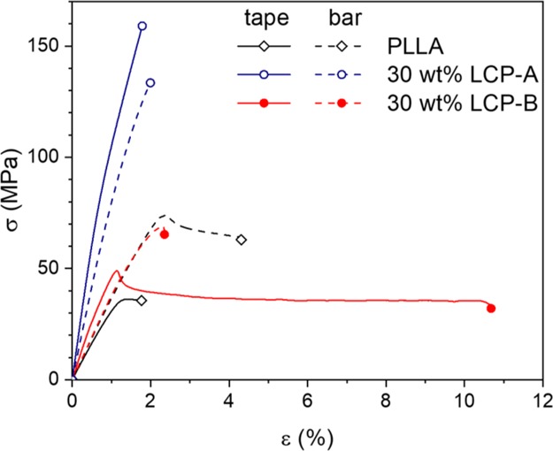
Characteristic stress–strain curves of produced tapes and injection-molded samples.
Conclusions
In this study, blends of two different thermotropic LCPs in PLLA are produced and the effect of the chosen processing routes is evaluated in terms of LCP morphology, LCP orientation, and composite mechanical properties. Elongated LCP fibrils with a high degree of interchain orientation result in effective reinforcement of the PLLA matrix, and are readily generated when the LCP/PLLA blends are melt drawn into tapes. In contrast, the morphology and performance of the LCP/PLLA blends proved significantly different when subjected to injection molding. From the findings in this work, the following design rules can be generated for the development of LCP materials for injection molding of thermoplastic LCP/PLLA blends:
In injection molding, the morphology of the extrudate and the thermal dependence of the flow behavior are found to be of importance. A very fine particle distribution can prove detrimental in achieving reinforcement: the shear-dominated flow field can be ineffective to deform small spherical droplets, therefore relying on coalescence in the initial stages of the process to allow the formation of fibrils. To this end, the matrix viscosity and the viscosity ratio are identified as key parameters in the extrusion process as they govern deformation and breakup of droplets in the complex flow field, and influencing both the resultant morphology and the particle size distribution. Therefore, the viscosity of the LCP component should be matched with the viscosity of the thermoplastic matrix (i.e., λ ≤ 1) to ensure the generation of LCP particles that can efficiently be deformed during injection molding.
Crystallization of the dispersed LCP is shown to hinder reinforcement during the injection molding process, as it induces a sudden increase in the viscosity ratio, destabilizing fibrils, and hindering deformation. Therefore, these findings suggest that the thermal behavior of LCP should be matched to the thermal behavior of the matrix under processing conditions: given the fact that PLLA does not crystallize during the injection molding process, the use of an amorphous LCP is preferred over the use of a semicrystalline LCP that crystallizes during the injection-molding process. More generally, it is concluded that a rapid increase in viscosity ratio during cooling, hampers the formation of a fibrillar morphology in a process that involves mostly shear flow.
In processes involving predominantly elongational flow, such as melt drawing, the viscosity ratio and its development with temperature is of less significance. An elongational flow field is more effective in deforming and stabilizing LCP fibrils, regardless of the viscosity ratio, and tapes with a highly oriented fibrillar LCP phase can readily be obtained.
The rheological findings in this work demonstrate that the LCP viscosity is of crucial importance for the interchain orientation and relaxation processes. The relaxation time of the LCP material is strongly governed by the contraction of the oriented nematic LCP domains, which is in turn enhanced by the application of increasing shear rates or decreasing LCP viscosity. Therefore, to maintain the LCP orientation during injection molding, the usage of a high viscosity LCP component is desired. As is observed for the injection molding of pure LCP-B, very low LCP viscosity results in a rapid loss of the induced interchain orientation during the injection molding process. Interestingly, this process does not seem to depend on the chemical structure of LCP, it only depends on the LCP viscosity (Figure 10 right).
As noted in the points before, the chemical composition of the LCP components does not directly affect the morphological development in the LCP/PLLA blends during processing, although it is an important factor with respect to the viscosity and thermal behavior of the LCP and interfacial tension of the blend. However, for a maximum reinforcement of the PLLA matrix, it is desired to take the intrinsic performance of the LCP material into account. In the ideal scenario, the thermoplastic LCP/PLLA composite will display performance according to the rule of mixtures, where the contribution of the LCP component is governed by its loading, its intrinsic mechanical performance, and its interchain orientation. To this end, the usage of fully aromatic thermotropic polyesters is desired as the presence of aliphatic spacers deteriorates both the maximum tensile modulus and tensile strength of the LCP component.
Acknowledgments
The research leading to these results has received funding by the H2020 Framework Program of the European Union under grant agreement no 685614.
Supporting Information Available
The Supporting Information is available free of charge on the ACS Publications website at DOI: 10.1021/acs.macromol.9b01083.
Additional information on parameters for the critical capillary number (κcritical), time–temperature superposition of PLLA, analyses of POM images of the blends in the barrel, microstructure of injection-molded samples containing 10 wt % LCP, and comparison of melt drawn and injection-molded samples (PDF)
The authors declare no competing financial interest.
Notes
Vectra LCP V400P grade is a registered trademark of Celanese Corporation, Dallas, TX. The material composition as well as the results associated with this material are the property of Celanese Corporation.
Supplementary Material
References
- Song Y. S.; Youn J. R.; Gutowski T. G. Life Cycle Energy Analysis of Fiber-Reinforced Composites. Composites, Part A 2009, 40, 1257–1265. 10.1016/j.compositesa.2009.05.020. [DOI] [Google Scholar]
- Pimenta S.; Pinho S. T. Recycling Carbon Fibre Reinforced Polymers for Structural Applications: Technology Review and Market Outlook. Waste Manag. 2011, 31, 378–392. 10.1016/j.wasman.2010.09.019. [DOI] [PubMed] [Google Scholar]
- Asmatulu E.; Twomey J.; Overcash M. Recycling of Fiber-Reinforced Composites and Direct Structural Composite Recycling Concept. J. Compos. Mater. 2014, 48, 593–608. 10.1177/0021998313476325. [DOI] [Google Scholar]
- Bassett B. R.; Yee A. F. A Method of Forming Composite Structures Usingin Situ-Formed Liquid Crystal Polymer Fibers in a Thermoplastic Matrix. Polym. Compos. 1990, 11, 10–18. 10.1002/pc.750110103. [DOI] [Google Scholar]
- Wang H.; Lee K. W.; Chung T.-S.; Jaffe M. Rheology, Morphology and Properties of LCP/Nylon 66 Composite Fibers. Polym. Compos. 2000, 21, 114–123. 10.1002/pc.10170. [DOI] [Google Scholar]
- Hassan A.; Yahya R.; Yahaya A. H.; Tahir A. R. M.; Hornsby P. R. Tensile, Impact and Fiber Length Properties of Injection-Molded Short and Long Glass Fiber-Reinforced Polyamide 6,6 Composites. J. Reinf. Plast. Compos. 2004, 23, 969–986. 10.1177/0731684404033960. [DOI] [Google Scholar]
- Fu S.-Y.; Lauke B.; Mäder E.; Yue C.-Y.; Hu X. Tensile Properties of Short-Glass-Fiber- and Short-Carbon-Fiber-Reinforced Polypropylene Composites. Composites, Part A 2000, 31, 1117–1125. 10.1016/s1359-835x(00)00068-3. [DOI] [Google Scholar]
- Chand S. Carbon Fibers for Composites. J. Mater. Sci. 2000, 35, 1303–1313. 10.1023/a:1004780301489. [DOI] [Google Scholar]
- Crist B. The Ultimate Strength and Stiffness of Polymers. Annu. Rev. Mater. Sci. 1995, 25, 295–323. 10.1146/annurev.matsci.25.1.295. [DOI] [Google Scholar]
- Kiss G. In situ composites: Blends of isotropic polymers and thermotropic liquid crystalline polymers. Polym. Eng. Sci. 1987, 27, 410–423. 10.1002/pen.760270606. [DOI] [Google Scholar]
- Blizard K. G.; Baird D. G. The Morphology and Rheology of Polymer Blends Containing a Liquid Crystalline Copolyester. Polym. Eng. Sci. 1987, 27, 653–662. 10.1002/pen.760270909. [DOI] [Google Scholar]
- Blizard K. G.; Federici C.; Federico O.; Chapoy L. L.; Caduti V. The Morphology of Extruded Blends Containing a Thermotropic Liquid Crystalline Polymer. Polym. Eng. Sci. 1990, 30, 1442–1453. 10.1002/pen.760302205. [DOI] [Google Scholar]
- Silverstein M. S.; Hiltner A.; Baer E. Hierarchical Structure in LCP/PET Blends. J. Appl. Polym. Sci. 1991, 43, 157–173. 10.1002/app.1991.070430113. [DOI] [Google Scholar]
- Economy J. Aromatic Polyesters ofp-Hydroxybenzoic Acid. Mol. Cryst. Liq. Cryst. 1989, 169, 1–22. 10.1080/00268948908062731. [DOI] [Google Scholar]
- Demus D.; Goodby J.; Gray G. W.; Spiess H. W.; Vill V.. Handbook of Liquid Crystals; Wiley-VCH, 1998. [Google Scholar]
- Collyer A. A. Thermotropic liquid crystal polymers for engineering applications. Mater. Sci. Technol. 1989, 5, 309–322. 10.1179/026708389790222474. [DOI] [Google Scholar]
- Yang Q.; Hirata M.; Hsu Y.-I.; Lu D.; Kimura Y. Improved Thermal and Mechanical Properties of Poly(Butylene Succinate) by Polymer Blending with a Thermotropic Liquid Crystalline Polyester. J. Appl. Polym. Sci. 2014, 131, 1–8. 10.1002/app.39952. [DOI] [Google Scholar]
- Yang Q.; Hirata M.; Lu D.; Nakajima H.; Kimura Y. Highly Efficient Reinforcement of Poly-l-Lactide Materials by Polymer Blending of a Thermotropic Liquid Crystalline Polymer. Biomacromolecules 2011, 12, 354–358. 10.1021/bm1011135. [DOI] [PubMed] [Google Scholar]
- Wilsens C. H. R. M.; Pepels M. P. F.; Spoelstra A. B.; Portale G.; Auhl D.; Deshmukh Y. S.; Harings J. A. W. Improving Stiffness, Strength, and Toughness of Poly(ω-pentadecalactone) Fibers through in Situ Reinforcement with a Vanillic Acid-Based Thermotropic Liquid Crystalline Polyester. Macromolecules 2016, 49, 2228–2237. 10.1021/acs.macromol.5b02419. [DOI] [Google Scholar]
- Auras R.Poly(Lactic Acid) Synthesis, Structures, Properties, Processing, and Application; Auras R., Lim L., Selke S., Tsuji H., Eds.; John Wiley & Sons, Inc.: Hoboken, 2010. [Google Scholar]
- Kricheldorf H. R.; Wahlen L.; Stukenbrook T. Biodegradable Liquid-Crystalline Aromatic Polyesters. Macromol. Symp. 1998, 130, 261–270. 10.1002/masy.19981300123. [DOI] [Google Scholar]
- Nagata M. Synthesis and Properties of Copolyesters Based on Hydroquinone, Sebacic Acid and p-Hydroxybenzoic Acid. High Perform. Polym. 2001, 13, S265–S274. 10.1088/0954-0083/13/2/323. [DOI] [Google Scholar]
- Du J.; Fang Y.; Zheng Y. Synthesis, Characterization and Biodegradation of Biodegradable-Cum-Photoactive Liquid-Crystalline Copolyesters Derived from Ferulic Acid. Polymer 2007, 48, 5541–5547. 10.1016/j.polymer.2007.07.040. [DOI] [Google Scholar]
- Tjong S. C. Structure, Morphology, Mechanical and Thermal Characteristics of the in Situ Composites Based on Liquid Crystalline Polymers and Thermoplastics. Mater. Sci. Eng., R 2003, 41, 1–60. 10.1016/s0927-796x(03)00035-4. [DOI] [Google Scholar]
- Chung T.-S. The Recent Developments of Thermotropic Liquid Crystalline Polymers. Polym. Eng. Sci. 1986, 26, 901–919. 10.1002/pen.760261302. [DOI] [Google Scholar]
- Picken S. J.; Sikkema D. J.; Boerstoel H.; Dingemans T. J.; van der Zwaag S. Liquid Crystal Main-Chain Polymers for High-Performance Fibre Applications. Liq. Cryst. 2011, 38, 1591–1605. 10.1080/02678292.2011.624367. [DOI] [Google Scholar]
- Acierno D.; La Mantia F. P.; Polizzotti G.; Ciferri A.; Valenti B. Ultra-high modulus liquid crystalline polyesters. p-Hydroxybenzoic acid copolyesters. Macromolecules 1982, 15, 1455–1460. 10.1021/ma00234a001. [DOI] [Google Scholar]
- Burghardt W. R.; Brown E. F.; Auad M. L.; Kornfield J. A. Molecular Orientation of a Commercial Thermotropic Liquid Crystalline Polymer in Simple Shear and Complex Flow. Rheol. Acta 2005, 44, 446–456. 10.1007/s00397-004-0424-1. [DOI] [Google Scholar]
- Beekmans F.; Gotsis A. D.; Norder B. Transient and steady-state rheological behavior of the thermotropic liquid crystalline polymer Vectra B950. J. Rheol. 1996, 40, 947. 10.1122/1.550788. [DOI] [Google Scholar]
- Kernick W. a.; Wagner N. J. The Role of Liquid-Crystalline Polymer Rheology on the Evolving Morphology of Immiscible Blends Containing Liquid-Crystalline Polymers. J. Rheol. 1999, 43, 521. 10.1122/1.551038. [DOI] [Google Scholar]
- Song C. H.; Isayev A. I. LCP Droplet Deformation in Fiber Spinning of Self-Reinforced Composites. Polymer 2001, 42, 2611–2619. 10.1016/s0032-3861(00)00555-3. [DOI] [Google Scholar]
- Heino M. T.; Hietaoja P. T.; Vainio T. P.; Seppälä J. V. Effect of Viscosity Ratio and Processing Conditions on the Morphology of Blends of Liquid Crystalline Polymer and Polypropylene. J. Appl. Polym. Sci. 1994, 51, 259–270. 10.1002/app.1994.070510208. [DOI] [Google Scholar]
- O’Donnell H. J.; Baird D. G. The Effect of Injection Molding Conditions on the Mechanical Properties of an in Situ Composite: Polypropylene and a Liquid Crystalline Copolyester Based on Poly(Ethylene Terephthalate) Co Poly(Hydroxybenzoic Acid). Int. Polym. Process. 1996, 11, 257–270. 10.3139/217.960257. [DOI] [Google Scholar]
- La Mantia F. P.; Cangialosi F.; Pedretti U.; Roggero A. Extrusion, Spinning and Injection Moulding of Blends of Poly(Ethylene Terephthalate) with Liquid Crystalline Polymers. Eur. Polym. J. 1993, 29, 671–677. 10.1016/0014-3057(93)90127-2. [DOI] [Google Scholar]
- Isayev A. I.; Modic M. Self-Reinforced Melt Processible Polymer Composites: Extrusion, Compression, and Injection Molding. Polym. Compos. 1987, 8, 158–175. 10.1002/pc.750080305. [DOI] [Google Scholar]
- Chan H. S.; Leng Y.; Gao F. Processing of PC/LCP in Situ Composites by Closed-Loop Injection Molding. Compos. Sci. Technol. 2002, 62, 757–765. 10.1016/s0266-3538(02)00051-9. [DOI] [Google Scholar]
- Mitchell G. R.; Windle A. H.. Orientation in Liquid Crystal Polymers. In Developments in Crystalline Polymers; Basset D. C., Ed.; Elsevier Applied Science: London, U.K., 1988. [Google Scholar]
- Ugaz V. M.; Burghardt W. R.; Zhou W.; Kornfield J. A. Transient Molecular Orientation and Rheology in Flow Aligning Thermotropic Liquid Crystalline Polymers. J. Rheol. 2001, 45, 1029–1063. 10.1122/1.1389317. [DOI] [Google Scholar]
- Einstein A. Eine neue Bestimmung der Moleküldimensionen. Ann. Phys. 1906, 324, 289. 10.1002/andp.19063240204. [DOI] [Google Scholar]
- Einstein A. Berichtigung Zu Meiner Arbeit: “Eine Neue Bestimming Der Molekuldimensionen.”. Ann. Phys. 1911, 339, 591. 10.1002/andp.19113390313. [DOI] [Google Scholar]
- Taylor G. I. The Viscosity of a Fluid Containing Small Drops of Another Fluid. Proc. R. Soc. A 1932, 138, 41–48. 10.1098/rspa.1932.0169. [DOI] [Google Scholar]
- Taylor G. I. The Formation of Emulsions in Definable Fields of Flow. Proc. R. Soc. A 1934, 146, 501–523. 10.1098/rspa.1934.0169. [DOI] [Google Scholar]
- Oldroyd J. G. The Elastic and Viscous Properties of Emulsions and Suspensions. Proc. R. Soc. London, Ser. A 1953, 218, 122–132. 10.1098/rspa.1953.0092. [DOI] [Google Scholar]
- Oldroyd J. G. The Effect of Interfacial Stabilizing Films on the Elastic and Viscous Properties of Emulsions. Proc. R. Soc. London, Ser. A 1955, 232, 567–577. 10.1098/rspa.1955.0240. [DOI] [Google Scholar]
- de Bruijn R. A.Deformation and Breakup of Drops in Simple Shear Flows; Eindhoven University of Technology, 1989. [Google Scholar]
- Søndergaard K.; Lyngaae-Jørgensen J. Coalescence in an Interface-Modified Polymer Blend as Studied by Light Scattering. Polymer 1996, 37, 509–517. 10.1016/0032-3861(96)82923-5. [DOI] [Google Scholar]
- Gauthier F.; Goldsmith H. L.; Mason S. G. Particle Motions in Non-Newtonian Media. Rheol. Acta 1971, 10, 344–364. 10.1007/bf01993709. [DOI] [Google Scholar]
- Wu S. Formation of Dispersed Phase in Incompatible Polymer Blends: Interfacial and Rheological Effects. Polym. Eng. Sci. 1987, 27, 335–343. 10.1002/pen.760270506. [DOI] [Google Scholar]
- Tomotika S. Breaking up of a Drop of Viscous Liquid Immersid in Another Viscous Fluid Which Is Extending at a Uniform Rate. Proc. R. Soc. London, Ser. A 1936, 153, 302–318. 10.1098/rspa.1936.0003. [DOI] [Google Scholar]
- Grace H. P. Dispersion Phenomena in High Viscosity Immiscible Fluid Systems and Application of Static Mixers As Dispersion Devices in Such Systems. Chem. Eng. Commun. 1982, 14, 225–277. 10.1080/00986448208911047. [DOI] [Google Scholar]
- Delaby I.; Ernst B.; Germain Y.; Muller R. Droplet Deformation in Polymer Blends during Uniaxial Elongational Flow: Influence of Viscosity Ratio for Large Capillary Numbers. J. Rheol. 1994, 38, 1705–1720. 10.1122/1.550568. [DOI] [Google Scholar]
- Delaby I.; Ernst B.; Froelich D.; Muller R. Droplet Deformation in Immiscible Polymer Blends during Transient Uniaxial Elongational Flow. Polym. Eng. Sci. 1996, 36, 1627–1635. 10.1002/pen.10559. [DOI] [Google Scholar]
- Huneault M. A.; Shi Z. H.; Utracki L. A. Development of Polymer Blend Morphology during Compounding in a Twin-Screw Extruder. Part IV: A New Computational Model with Coalescence. Polym. Eng. Sci. 1995, 35, 115–127. 10.1002/pen.760350114. [DOI] [Google Scholar]
- Elemans P. H. M.Modelling of the Processing of Incompatible Polymer Blends, Eindhoven University of Technology, 1989. [Google Scholar]
- Shi Z. H.; Utracki L. A. Development of polymer blend morphology during compounding in a twin-screw extruder. Part II: Theoretical derivations. Polym. Eng. Sci. 1992, 32, 1834–1845. 10.1002/pen.760322406. [DOI] [Google Scholar]
- Utracki L. A.; Shi Z. H. Development of polymer blend morphology during compounding in a twin-screw extruder. Part I: Droplet dispersion and coalescence?a review. Polym. Eng. Sci. 1992, 32, 1824–1833. 10.1002/pen.760322405. [DOI] [Google Scholar]
- Kamal M. R.; Utracki L. A.; Mirzadeh A.. Rheology of Polymer Alloys and Blends. In Polymer Blends Handbook; Utracki L. A., Wilkie C., Eds.; Spring Netherlands: Dordrecht, 2014; Vol. 2, pp 726–853. [Google Scholar]
- Bordereau V.; Carrega M.; Shi Z. H.; Utracki L. A.; Sammut P. Development of Polymer Blend Morphology During Compounding in a Twin-Screw Extruder. Part III: Experimental Procedure and Preliminary Results. Polym. Eng. Sci. 1992, 32, 1846–1856. 10.1002/pen.760322407. [DOI] [Google Scholar]
- Wilsens C. H. R. M.; Verhoeven J. M. G. A.; Noordover B. A. J.; Hansen M. R.; Auhl D.; Rastogi S. Thermotropic Polyesters from 2,5-Furandicarboxylic Acid and Vanillic Acid: Synthesis, Thermal Properties, Melt Behavior, and Mechanical Performance. Macromolecules 2014, 47, 3306–3316. 10.1021/ma500433e. [DOI] [Google Scholar]
- Anastasiadis S. H.; Gancarz I.; Koberstein J. T. Interfacial Tension of Immiscible Polymer Blends: Temperature and Molecular Weight Dependence. Macromolecules 1988, 21, 2980–2987. 10.1021/ma00188a015. [DOI] [Google Scholar]
- Elemans P. H. M.; Janssen J. M. H.; Meijer H. E. H. The Measurement of Interfacial Tension in Polymer/Polymer Systems: The Breaking Thread Method. J. Rheol. 2002, 34, 1311–1325. 10.1122/1.550087. [DOI] [Google Scholar]
- Wu S. Calculation of Interfacial Tension in Polymer Systems. J. Polym. Sci., Part C: Polym. Symp. 1971, 34, 19–30. 10.1002/polc.5070340105. [DOI] [Google Scholar]
- de Kort G.; Leoné N.; Stellamanns E.; Auhl D.; Wilsens C.; Rastogi S. Effect of Shear Rate on the Orientation and Relaxation of a Vanillic Acid Based Liquid Crystalline Polymer. Polymers 2018, 10, 935. 10.3390/polym10090935. [DOI] [PMC free article] [PubMed] [Google Scholar]
- Langelaan H. C.; Gotsis A. D. The Relaxation of Shear and Normal Stresses of Nematic Liquid Crystalline Polymers in Squeezing and Shear Flows. J. Rheol. 1996, 40, 107. 10.1122/1.550733. [DOI] [Google Scholar]
- Qian C.; Baird D. G. The Transient Shear Rheology of a Thermotropic Liquid Crystalline Polymer in the Super-Cooled State. Polymers 2016, 102, 63–72. 10.1016/j.polymer.2016.08.056. [DOI] [Google Scholar]
- Onogi S.; Asasda T.. Rheology and Rheo-Optics of Polymer Liquid Crystals. In Rheology; Astarita G., Marrucci G., Nicolais L., Eds.; Springer: Boston, 1980; pp 127–147. [Google Scholar]
- Lovell C. S.; Montes de Oca H.; Farrar D.; Ries M. E.; Ward I. M. Analysis and Modeling of the Mechanical Properties of Novel Thermotropic Polymer Biomaterials. Polymer 2010, 51, 2013–2020. 10.1016/j.polymer.2010.02.047. [DOI] [Google Scholar]
Associated Data
This section collects any data citations, data availability statements, or supplementary materials included in this article.


