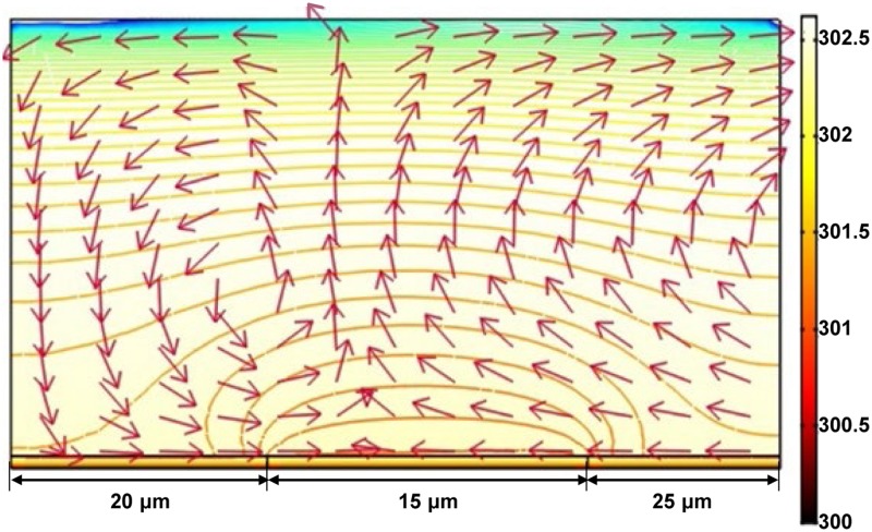
FIG. 5.
FEA results of how the ACET flow is spatially distributed in the OEK chip. The arrow and the surface color represent the direction of the ACET flow and the temperature distribution (unit: K) in the vertical direction of the OEK chip. The isolines represent the logarithmic distribution of the temperature gradient, with an interval value of 0.15 between any two adjacent isolines. Reproduced with permission from Liang et al., in 2011 IEEE International Conference on Nano/Micro Engineered and Molecular Systems (NEMS) (IEEE, 2011), p. 825. Copyright 2011 IEEE Publishing.

