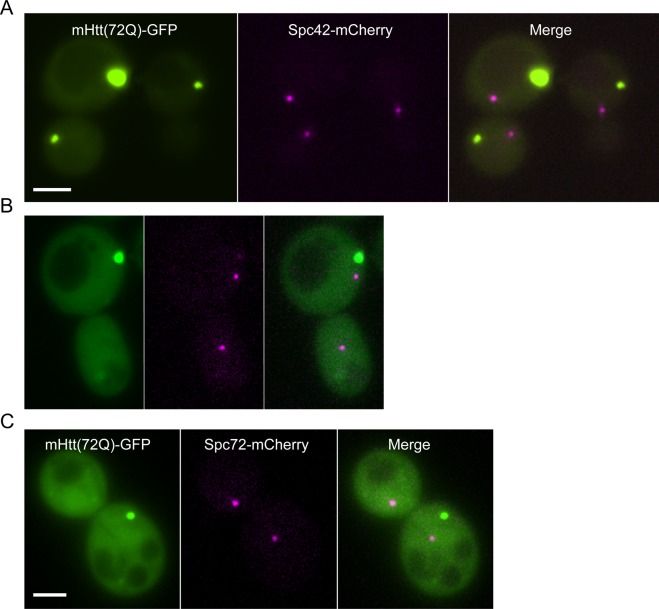
Figure S7. The localization of mutant Htt IBs with regard to the spindle-pole body.
(A) Mutant Htt(72Q)-GFP (green) co-expressed in cells with an integrated Spc42-mCherry reporter fusion (magenta). The GFP-tagged IBs and mCherry-tagged spindle poles are visible in different planes. The merged image demonstrates the lack of co-localization in the x–y plane; the magenta and green images are also 1.6 μm apart along the z-axis. (B) Mutant Htt(103Q)-GFP (green) co-expressed in cells with an integrated Spc42-mCherry reporter fusion (magenta). The magenta image is a maximum projection as the two mCherry-tagged spindle poles were visible in planes that were 600 nm apart; in this case, the IB, which is much larger than a spindle pole, was visible in the same planes as the two spindle poles. (C) Mutant Htt(72Q)-GFP (green) co-expressed in cells with an integrated Spc72-mCherry reporter fusion (magenta). The magenta image is a maximum projection as the two mCherry-tagged spindle poles were visible in planes that were 300 nm apart; in this case, the IB was visible in the same planes as the two spindle poles. The scale bar represents 2 μm in (A–C).

