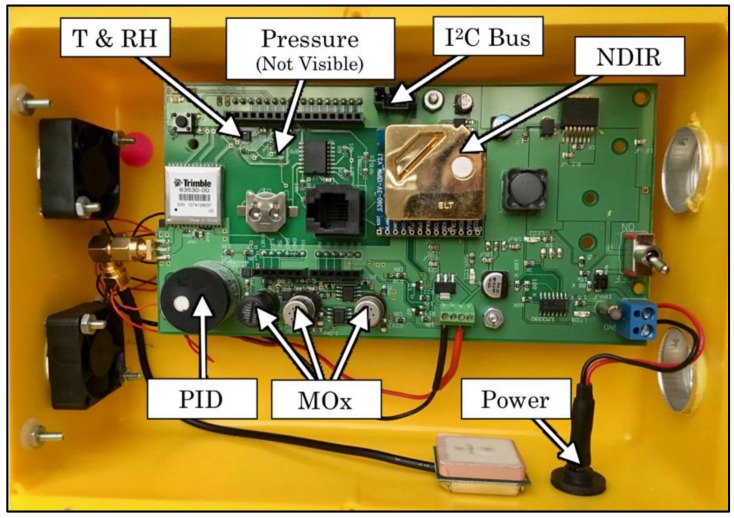
Figure 1.
Image of a typical Y-Pod with important components labeled. The connector that is labeled “I2C bus” was used both to communicate with ancillary sensor boards and to provide power to those boards. The boards were not installed in the ventilated box shown in this photo but were instead placed directly into the test chamber.

