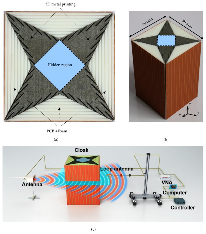
Figure 3.
Photographs of the fabricated cloak and scheme of the experiment setup. (a) Top view of the metamaterial cloak. The extreme metamaterial is realized with the standard commercial 3D metal printing technology and the non-extreme one is implemented with the PCB-Foam layered structures. (b) Perspective view of the metamaterial cloak with 8 unit cells in the z direction. (c) Scheme of the experiment setup. An open X-band rectangular waveguide with z-polarized magnetic field, located at a distance of 50 mm away from the cloak, is used as a source. A loop antenna with a radius of 4 mm is used as the receiving antenna. Both transmitting and receiving antennas are connected to a VNA to obtain the amplitude and phase of the measured field. The measuring loop antenna is attached to a mechanical arm of a 3D measurement platform and can be controlled to move in the xy planes to point-to-point probe the magnetic field. The scan region (the light-blue rectangle) is 300 mm by 236 mm with a resolution of 4 mm.

