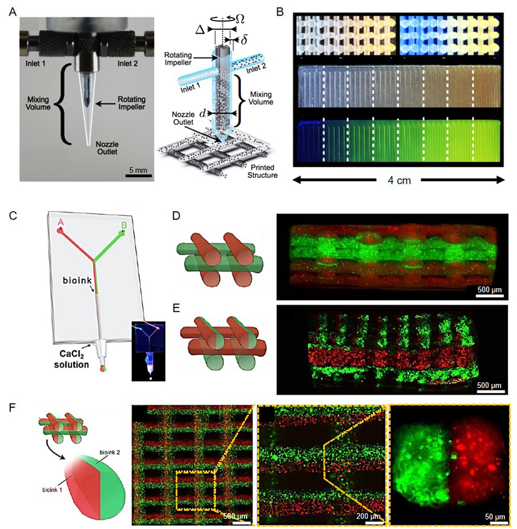
Figure 10.

Multi-material bioprinting of cell-laden tissue constructs. (A) Optimal image and schematic of an impeller-based active mixer printhead. (B) (Top) Images of the cross-section of a 3D rectangular lattice structure of showing continuous change in fluorescent pigment concentration under (left) bright light and (right) UV radiation. (Bottom) Images of a 2D carpet structure showing a discretely varying fluorescent gradient at eight different mixing ratios under (top) bright light and (bottom) UV radiation. Reproduced with permission from ref.[173]. (C) Schematic of a microfluidic system to separate two bioinks while extrusion trough a single nozzle. (D-F) Schematics and fluorescence microscopy images of cross-section views of 3D construct with (D) alternative deposition, (E) alternative/simultaneous deposition, and (F) simultaneous deposition. Reproduced with permission from ref.[69].
