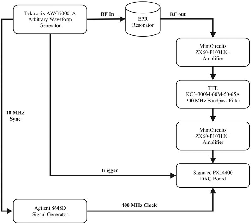
Fig. 3.
Block diagram of EPR system. In this experimental setup, a Tektronix AWG70001 arbitrary waveform generation is the RF excitation source. An Agilent 8648D is synchronized with the AWG to provide a synchronized clock to the Signatec PX14400 data acquisition board. The RF excitation is input into a custom in-house EPR cross-coil resonator. The RF response from the resonator is amplified and filtered before being acquired by the data acquisition board.

