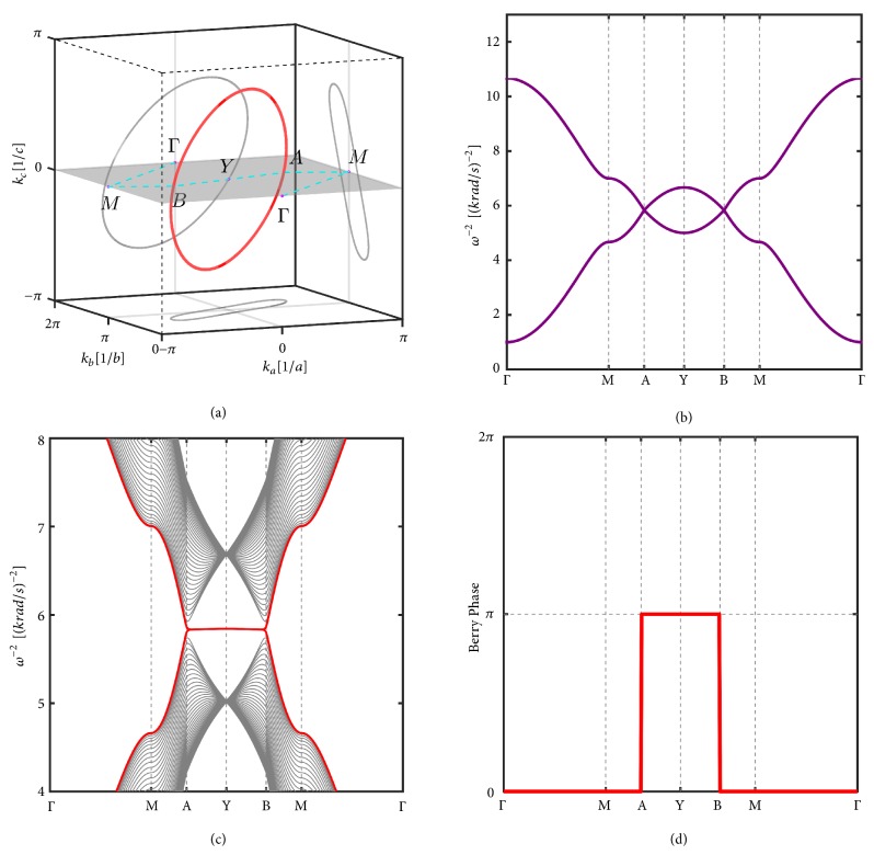
Figure 2.
(a) Nodal line (in red) in the BZ and its projection on the (001), (010), and (100) planes (in grey). The parameters are set as C1 = 1mF, C2 = 2mF, C3 = 1mF, C4 = 0.833mF, CGA = CGB = 1mF, and LA = LB = 1mH. (b) Band structure along Γ − X − A − B − X − Γ, where A and B are two points with kc = 0 on the nodal line as labeled in (a). (c) The band dispersions with the surface states (red colour lines) on the (001) surface. The drumhead-like surface states are nestled inside the projection of the nodal ring. (d) The Berry phase θk|| equals π for k|| inside the nodal ring, while it is zero for k|| outside the nodal ring.

