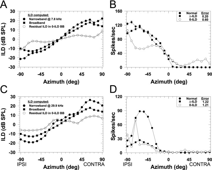
Fig. 8.
ILDs as a function of azimuth computed under three different conditions and associated spatial receptive fields for two LSO cells. In A and C, the filled circles indicate the ILD as seen through a 1/3-octave Gaussian narrowband filter centered on the CFs of the cells whose spatial receptive fields are shown in Figures 3 (CF, 7.8 kHz) and 4 (CF, 29.9 kHz), respectively. Negative ILDs indicate that sounds at the ipsilateral ear exceed the level at the contralateral ear. Thefilled squares show the broadband ILD computed across the entire spectrum and is thus the same in both A andC. The open circles show the “residual” ILD as a function of azimuth through the 1/3-octave filter at CF in the broadband 0-ILD condition. Note that although the broadband ILD is 0 dB at all azimuths (data not shown), there are nonzero ILDs occurring in narrow bands of frequencies around these and other CFs. B,D, Spatial receptive fields in azimuth for the normal condition and the broadband ILD cue manipulation conditions for the cells shown in Figures 3 and 4. Same format as in Figure 3.

