
Figure 1.
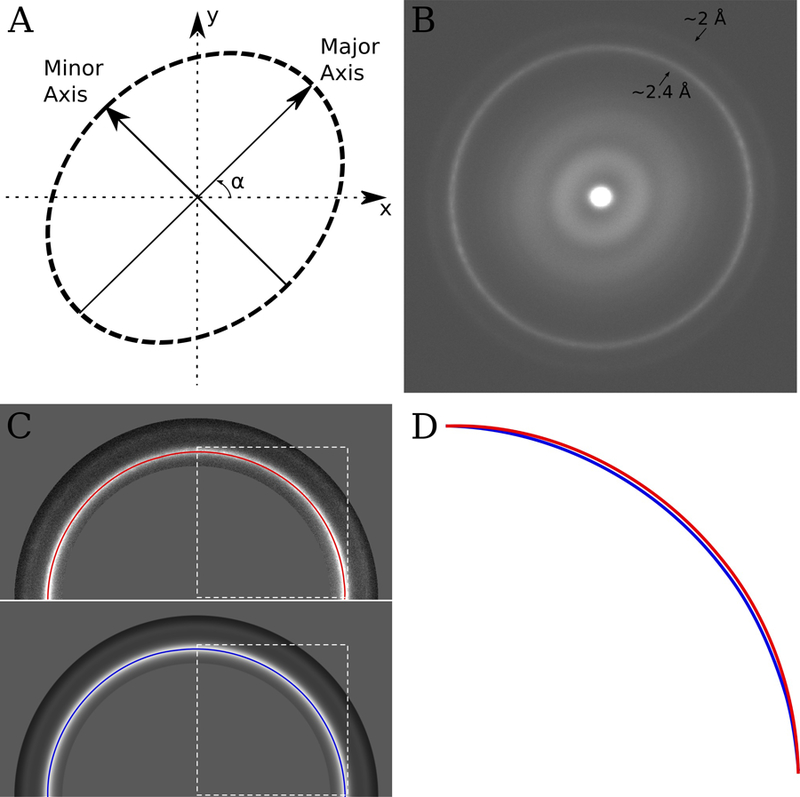
(A) An anisotropic magnification distortion can be described with 3 parameters (in this case, two scale factors which describe the scaling along the major and minor axes and α, which describes the orientation of the major axis). (B) Sum of the amplitude spectra from 10 images of a polycrystalline gold covered diffraction grating. The images were taken at a nominal magnification of 22,500 on an FEI Titan Krios. The ~2.4 Å and ~2 Å gold rings are visible in the image and are slightly elliptical suggesting anisotropic magnification. (C) Top – half of the image shown in B, with the gold rings masked out and a path tracing the ~2.4 Å gold ring. Bottom – half of the rotational average of the image shown in B, also with the gold rings masked out and a path tracing the ~2.4 Å gold ring. The dashed white box illustrates the area, which is shown zoomed and overlaid in panel D. (D) Overlay of the section of the paths traced in C surrounded by the dashed white box. The path from the original image is different compared with the rotationally averaged version, indicating anisotropic magnification. In this instance the difference is ~1%, which combined with a ~1% difference in the orthogonal direction indicates a ~2% anisotropic magnification distortion at this magnification.