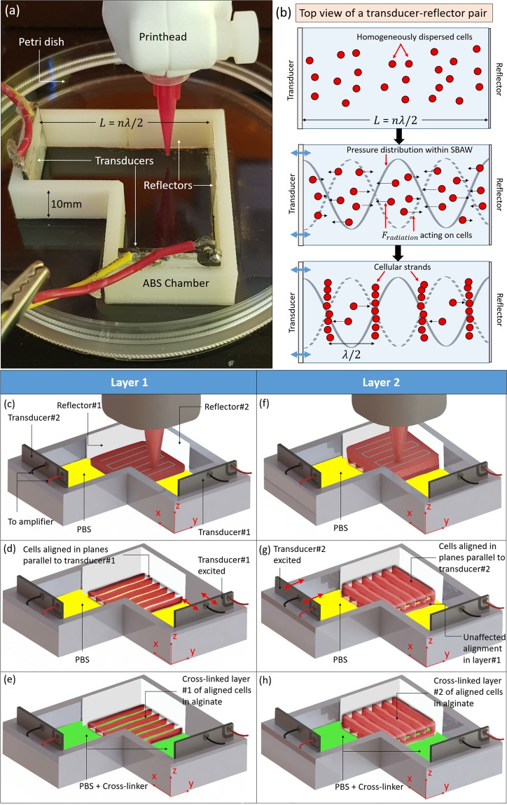
Figure 1.
Ultrasound-assisted bioprinting. (a) The cross-patterning ultrasound alignment chamber that contains orthogonally arranged transducer-reflector pairs. (b) Schematic representation of the SBAW generated due to transducer excitation, and the resulting acoustic pressure distribution which exerts Fradiation on the cells to align them at the pressure nodes of the SBAW. (c) The bioink is printed as adjacent strands (blue lines depict that rectilinear pattern of deposition) into the chamber pre-filled with PBS buffer to constitute the first layer of the construct. The MG63 are homogeneously distributed across this layer. (d) Transducer #1, when excited using a sinusoidal voltage signal, vibrates along its thickness (along x-axis) to align the cells along nodal planes parallel to the transducer surface (y-z plane). (e) The alginate is gradually crosslinked by introducing the crosslinker (CaCl2) to entrap the aligned cells within the first layer. (f) The second layer of bioink is printed on top of the crosslinked first layer after aspirating all the fluid (PBS + CaCl2) in the chamber and adding fresh PBS. (g) Transducer#2, when excited using a sinusoidal voltage signal, vibrates along its thickness (along y-axis) to impart an orthogonal cellular alignment (x-z plane) relative to the first layer (0°–90° alignment). (h) The crosslinker (CaCl2) is introduced to gradually crosslink the second alginate layer while entrapping the aligned cells. Note that since the viscosity of crosslinked alginate is several orders of magnitude higher than its uncrosslinked solution counterpart71, the alignment of cells entrapped within the crosslinked first layer is not affected by transducer excitation during printing and alignment of the subsequent layer. To achieve parallel alignment (0°–0°) across layers, either transducer#1 or transducer#2 can be excited after depositing each layer.

