
Fig. 4.
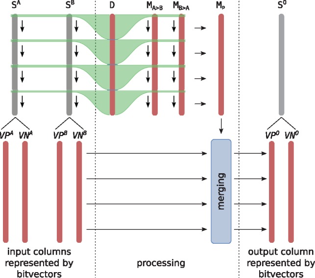
Conceptual idea of bit-vector merging. Red bars represent bit-vectors, which are stored in memory. Gray bars represent input/output columns, which are never stored explicitly, but represented implicitly by the respective bit-vectors. The variable D is split into chunks of size , where the bits in each chunk encode the difference between a particular row in SA and SB, as indicated by green lines. The values in each chunk are used to compute the respective bits in and . In each iteration, the chunks are updated to represent a difference of SA and SB one row further down, indicated by down arrows. Once and have been computed, the ‘picking mask’ Mp is computed in parallel (horizonal arrows) and used in the final merging step (blue box)