
Fig. 1.
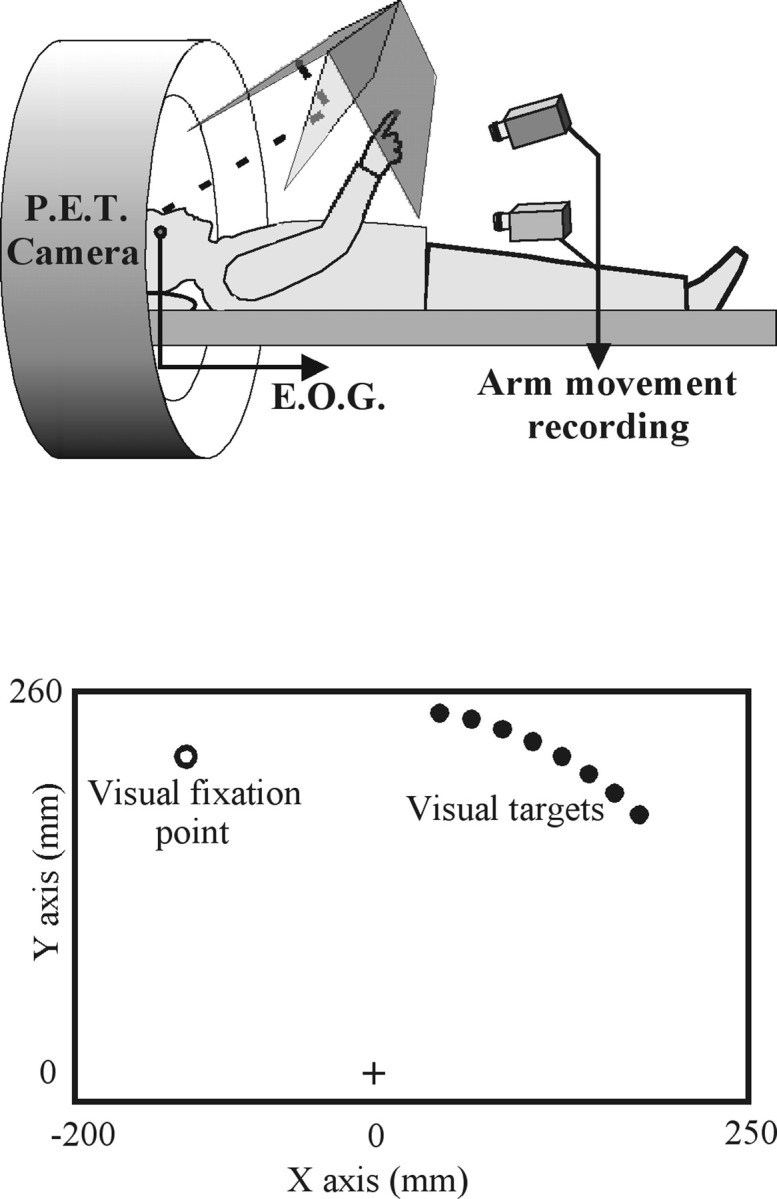
A, Schematic representation of the experimental apparatus. Subjects were supine with their head immobilized in the scanner. A pointing board was placed in front of them. An array of LEDs and a half-reflecting mirror were suspended over the pointing board. The subjects saw the virtual image of the LEDs (targets) through the mirror, in the plane of the board.B, Schematic representation of the pointing board. Nine LEDs were used in the present experiment. They were located on a circle (radius, 250 mm; center, the hand starting point). One green diode (white circle) was located in the left hemispace at −30° (visual fixation point). Eight red diodes (black circles) were located in the right hemispace with a 5° increment from 10 to 45° (targets).