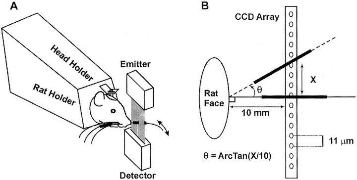
Fig. 1.
A, Schematic diagram of the optoelectronic monitoring system, indicating the position of the laser emitter and detector with respect to the head-fixed animal. In these experiments, all whiskers were intact on both sides of the face, and the right and left C-1 whiskers were marked for monitoring. For clarity, only a single set of emitters and detectors and only a single whisker are shown on one side of the face. B, Schematic diagram illustrating both the basic principle of the monitoring system and the process by which whisker displacements are transformed from CCD units to angular whisker positions. Thick black linesindicate the successive positions of the marked vibrissa during a whisking movement.

