
Fig. 1.
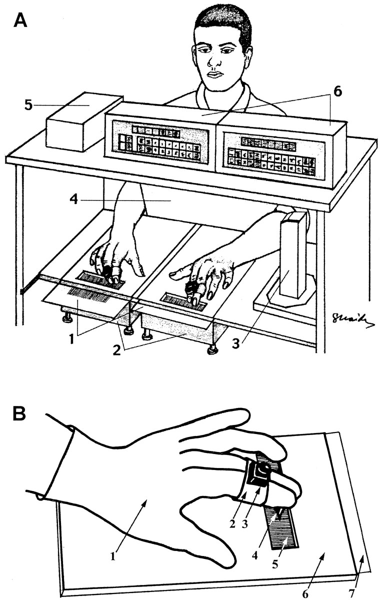
Experimental apparatus. A, General scheme. 1, Grating surfaces; 2,electronic scales; 3, component of the location detector containing infrared transmitter and ultrasonic receiver;4, screen; 5, interface box of the location detector; and 6, monitors and computer interface of electronic scales. B, Scanning with gloves.1, Latex glove; 2, Velcro band holding the sensor of the location detector; 3, sensor of the location detector; 4, rubber pin; 5,grating; 6, Plexiglas board; and 7,grating surface (inserted underneath the Plexiglas board).