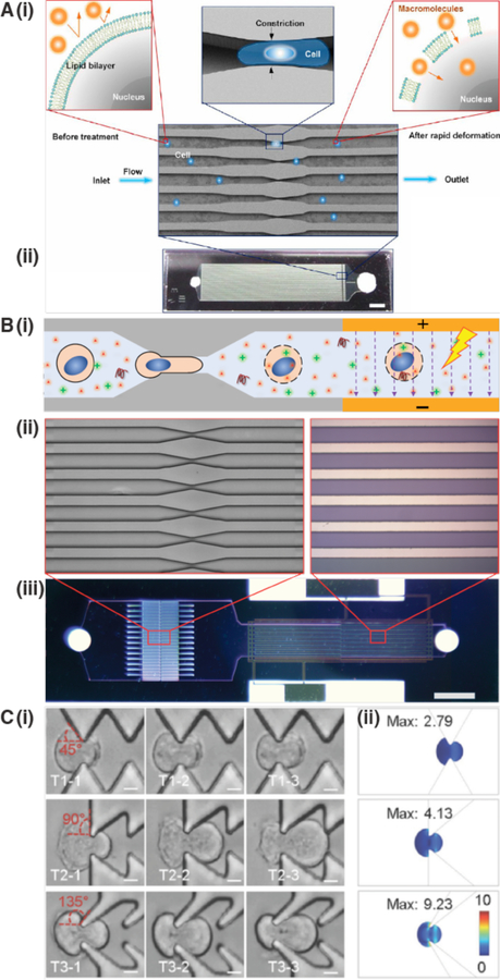
Figure 16.
Different variations of cell squeezing for membrane permeabilization. (A) The original microfluidic platform for cell squeezing184. (i) The deformation the cell experiences upon passage through the constriction transiently permeabilizes the plasma membrane, allowing influx of cargo molecules into the cytosol. (ii) microfluidic chip, consisting of a silicon parallel microchannels produced by deep reactive ion-etching and sealed from the top with glass. Inlets and outlets are also visible. (B) Similar to cell squeezing in panel A but with addition of a downstream electric field. The electric field enhances delivery of large nucleic acids, such as plasmid DNA, into the cell by electrophoretic forces. In this case the device was optimized for delivery of plasmids into the cell nucleus at high throughput749. Panel (i) shows the delivery concept. Panel (ii) shows the architecture of the constriction and electrode zones. Panel (iii) shows a view of the whole chip. (C) Cell squeezing with different constriction geometries in PDMS device. (i) Comparison of 45° pyramidal pattern, 90° saw tooth pattern, and 135° reverse wishbone pattern of repeated constrictions. (ii) COMSOL modeling indicates the stress (N·m−2) that the cell membrane undergoes upon passage through the different types of constrictions. Experiments and modeling showed the reverse wishbone pattern as the most effective for membrane disruption in this platform750.

