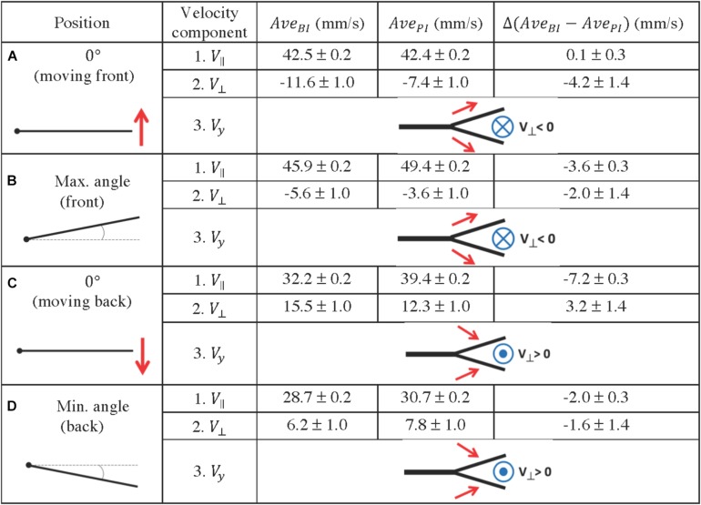
FIGURE 11.
Quantification of fluid profiles in the bifurcation interray zone (BI) and the primary interray zone (PI), at four equidistant positions of the fin model during a complete period. (A–D) Four key points were selected along a full period of oscillation as indicated in the left column. A schematic depiction of the vertical velocity component (Vy) is represented by the simplified diagrams in the right column, in which the red arrows symbolize the Vy vectors, pointing toward or away from the bifurcation region. The blue symbols represent the resulting fluid motion in the perpendicular direction, namely the V⊥ vectors, pointing outward (circle with a dot in the middle) or inward (circle with a cross in the middle). The average velocity components parallel and perpendicular to the plate (V// and V⊥) are indicated in millimeters per second. They are noted AveBI or AvePI depending on the averaging surface (BI region or PI region), and the difference between the averages Δ(AveBI – AvePI) is also shown.

