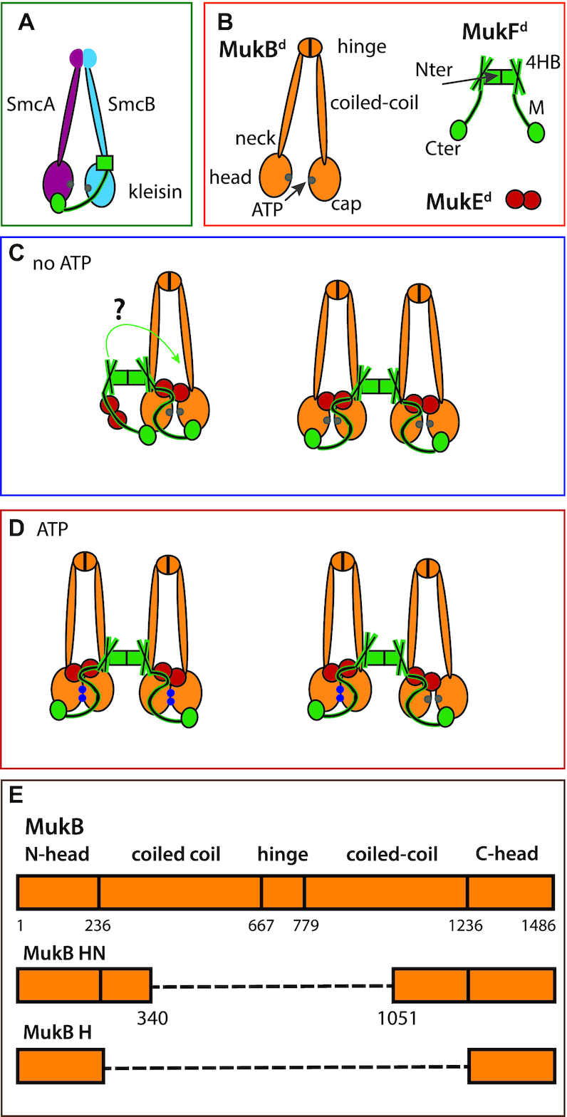
Figure 1.

Schematics showing conserved SMC architectures and possible MukBEF stoichiometries and architectures. (A) Generic SMC complex architecture showing the tripartite proteinaceous ring formed by the kleisin and SMC proteins. (B) The components of the MukBEF complex. (C and D) Possible MukBEF architectures, without (C) and with (D) ATP. In D, the right panel shows a possible complex after ATP is hydrolysed in one of the dimers of a dimer of dimer complex. When ATP-dependent heads engagement occurs, the MukF middle region blocks the binding of a second MukF C-terminal domain to the second MukB head of a MukB dimer (27). When heads are unengaged, each MukB head can bind a MukF C-terminal domain, potentially leading to ‘daisy chain’ forms of a higher complexity than dimers and dimers of dimers (not shown). ATP-bound ATPase active sites denoted as blue dots on the heads and ADP-bound or nucleotide-unbound as grey dots. (E) Schematic showing MukB and its truncated variants head neck (HN) and head (H); a dashed line indicates a linker connecting N-and C-terminal head domains.
