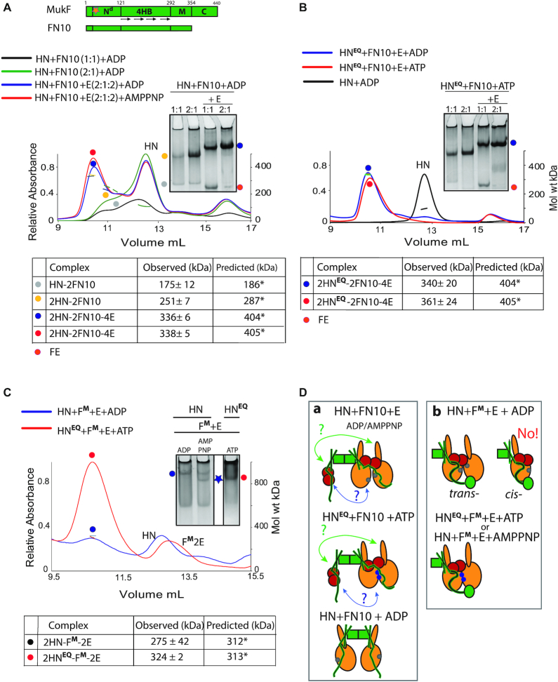
Figure 4.
Architecture of MukBEF complexes. (A) Top, schematic of MukF and its truncated derivative FN10; Nd, N-terminal dimerisation domain; 4HB, 4-helix bundle; M, middle region; and C, C-terminal domain, which is deleted in FN10. Orange star indicates position of dimerisation interface, which has been altered in MukFM; also see (Figure 6). (A andB) SEC-MALS and native PAGE analyses of HN and HNEQ complexes generated with FN10 dimers. For SEC-MALS, samples at the indicated protein ratios were incubated with ADP, AMPPNP or ATP before separation through a Superose 200 column. FN10 was at 5 μM and E, when present, was 10 μM. Predicted and observed masses of complexes are tabulated below traces. Native gel samples were incubated with ADP (A) or ATP (B) prior to loading onto a gel. (C) SEC-MALS and native PAGE analyses of HN and HNEQ complexes generated with FM-E in the presence of ADP, AMPPNP or ATP as indicated. The proteins were at concentrations of 10 μM HN/HNEQ, 5 μM FM and 10 μM E. (A–C) Significant (<16%) differences in observed to predicted masses of the complexes in some experiments are due to incomplete resolution of the complexes from unbound HN. (D) Schematics of the proposed architectures with FN10 (panel a) and MukFM (panel b). The green arrows (a) indicate a possible interaction between the FN10 4HB and the neck of the distal HN molecule. A second potential interaction between the ‘free’ FN10 middle region and its bound MukE to the proximal HN molecule is indicated by blue arrows. The bottom cartoon in (a) shows two HN molecules binding a FN10 dimer through interactions with the 4HBs. ATP-bound ATPase active sites denoted as blue dots on the heads and ADP-bound or nucleotide-unbound as grey dots.

