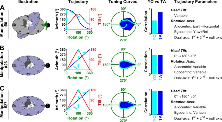
Fig. 9.
Analysis of Shinder and Taube’s (2019) manipulations: complex rotations. Same format as in Fig. 6. As in Fig. 8, tilted azimuth (TA) is not defined at 180° tilt in B and C, but the corresponding curve (Trajectory panels, blue) appears uninterrupted since TA is defined in the vicinity of this point. Manipulations 8 (A), 26 (B), and 27 (C) are animated in Supplemental Movie S4, available at https://github.com/JeanLaurens/Modelling-3D-HD-Cell-Tuning. YO, yaw only.

