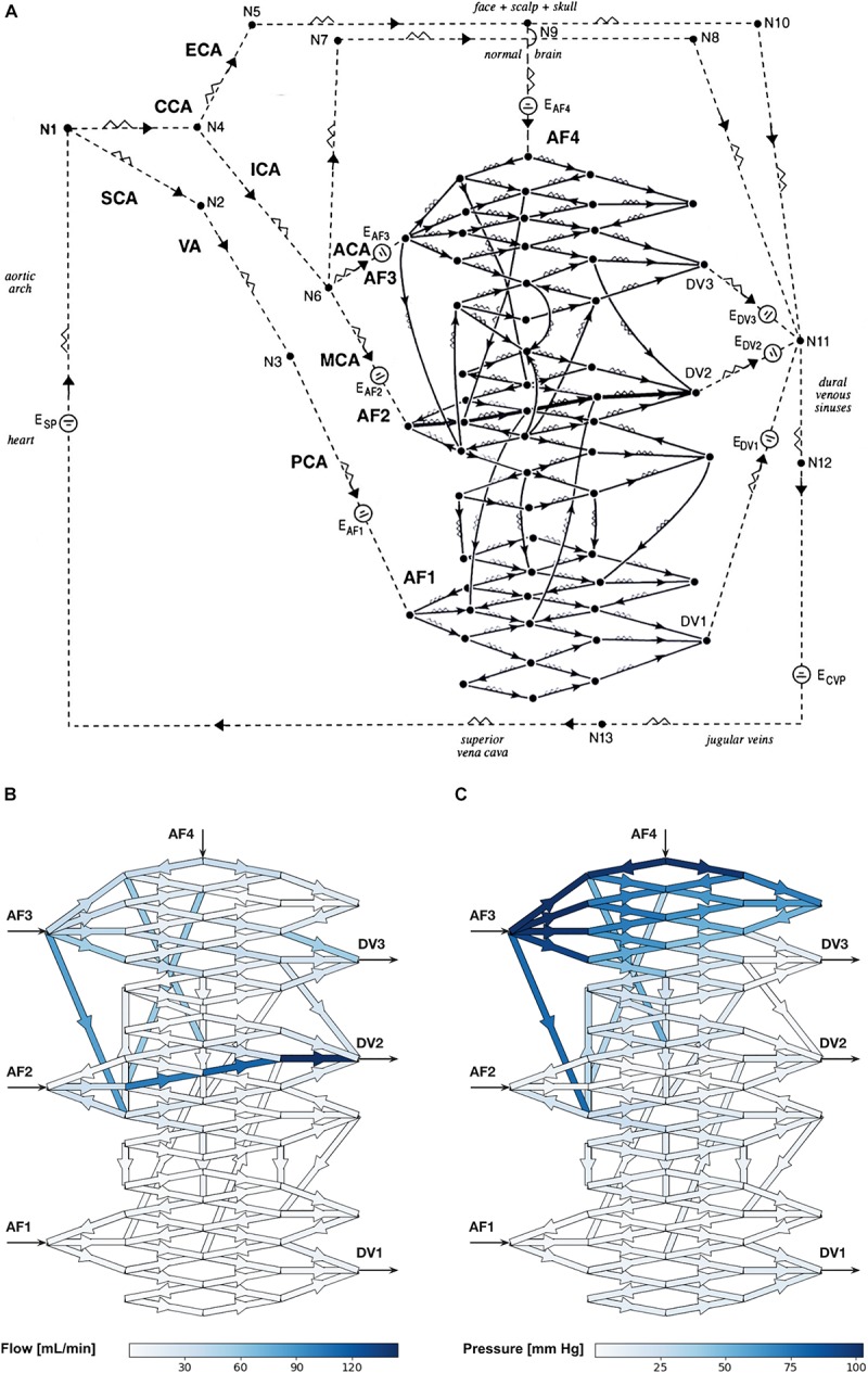
FIGURE 1.

(A) Schematic diagram of the electrical circuit showing the biomathematical AVM model and the details of the 3-D AVM nidus network. AF, arterial feeder; DV, draining vein; CCA, common carotid artery; ECA, external carotid artery; ICA, internal carotid artery; SCA, subclavian artery; VA, vertebral artery; PCA, posterior cerebral artery; ACA, anterior cerebral artery; MCA, middle cerebral artery; E, electromotive force; N, node; CVP, central venous pressure. The intranidal fistula spans AF2 to DV2. Arrowheads indicate direction of flow. (B,C) Hemodynamic simulations using the biomathematical 3-D AVM model in its baseline state. (B) Simulated intranidal volumetric flow rate through the nidus (color scale in mL/min). (C) Simulated intranidal Pmean through the nidus (color scale in mm Hg). AF, arterial feeder; DV, draining vein.
